FIR 1-D Digital Filter Design (The Window Method):
We describe the Fourier series technique as the first design method of 1-D FIR digital filters [Eq. (15.83)]. In this Digital Filter Design Window Method, given a frequency function H(ejω) with period 2π, an FIR Digital Filter Design Window Method with a transfer function corresponding to H(ejω) can be obtained by simply computing the coefficients of the Fourier series of H(ejω) and using these coefficients as the impulse response of the filter.
The main problem is that in general the Fourier series so obtained has an infinite number of coefficients, resulting in a filter which cannot be implemented. It is therefore necessary, in this case to truncate the Fourier series so obtained in some way. This truncation unfortunately leads to Gibb’s phenomenon, which causes the appearance of an overshoot in the approximated frequency response near a discontinuity.
To illustrate this point, let us consider the design of a low pass filter whose ideal response is as shown in Fig. 15.32(a). The magnitude of this filter is defined equal to unity in the interval (0 – ωc) and equal to zero in the interval ωc– π.The impulse response {h(n)} can be obtained by computing the coefficients of the Fourier series for H(ejω), which are given by
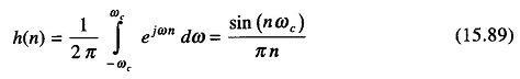
This response has the form shown in Fig. 15.32 (b) for N = 101 (where N = number of impulse response).
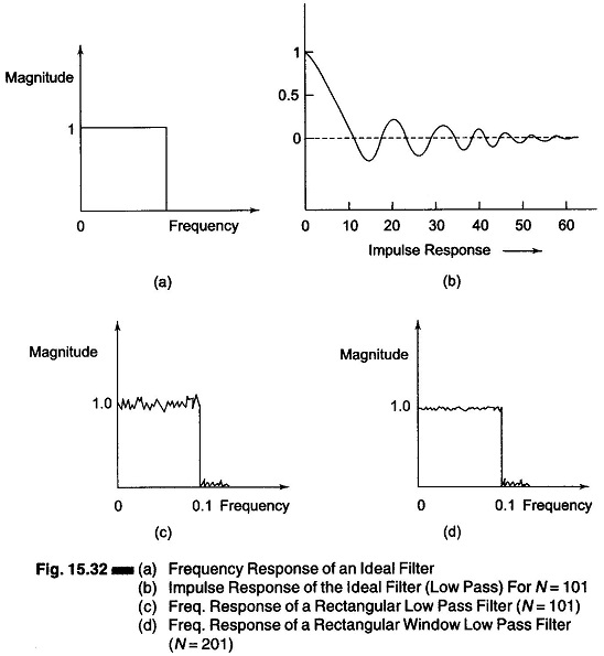
If now we consider the frequency transfer function of the filter resulting from a truncated Fourier series whose coefficients are as shown in Fig. 15.32(b), i.e., Eq. (15.89), we obtain the result shown in Fig. 15.32(c).
Figure 15.32(c) shows the amount of the error due to Gibb’s phenomenon and the fact that a finite transition band substitutes for the discontinuity in the ideal frequency response.
The error introduced by the transition of the Fourier series, which in the case of an ideal low pass filter or band pass filter is 9% of the value of discontinuity, is independent of the length of the impulse response.
When the impulse response is lengthened, the maximum error is the same but the oscillations are confined to a smaller frequency range, as can be seen in Fig. 15.32(d), where the transfer function of the low pass filter with N = 201 is shown.
The Digital Filter Design Window Method can also be directly applied to the design of 2-D FIR filters.
A 2-D filter with a frequency response H(ejω1 ejω2), periodic in ω1 and ω2 can be synthesized by using a impulse response, the sequence {h(n1, n2)} obtained by computing the coefficients of a 2-D Fourier series of the periodic frequency response.