Megger Circuit Diagram

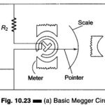
Megger Circuit Diagram: Another common method of measuring resistances above 50 M Ω is the Megger Circuit Diagram (megaohmmeter) shown in Fig. 10.23(a). This instrument is used to measure very…

Continue Reading Megger Circuit Diagram

Fibre Optic CRT Recording Oscilloscope

Fibre Optic CRT Recording Oscilloscope: Fibre Optic CRT Recording Oscilloscope - The familiar CRT oscilloscope has an extremely HF response, but permanent records, normally photography of the screen, cannot be…

Continue Reading Fibre Optic CRT Recording Oscilloscope

Dual Trace Oscilloscope

Dual Trace Oscilloscope: Figure 7.19 (a) shows a block diagram of Dual Trace Oscilloscope. This CRO has a single electron gun whose electron beam is split into two by an…

Continue Reading Dual Trace Oscilloscope

Vertical Amplifier

Vertical Amplifier: The sensitivity (gain) and frequency bandwidth (B.W.) response characteristics of the oscilloscope are mainly determined by the vertical amplifier. Since the gain B.W. product is constant, to obtain…

Continue Reading Vertical Amplifier

Block Diagram of CRO

Block Diagram of CRO: The Basic Block Diagram of CRO is shown in Fig.7.5. The ac filament supplies power to the CRT heaters in the Block Diagram of CRO. This…

Continue Reading Block Diagram of CRO

Block Diagram of Oscilloscope

Block Diagram of Oscilloscope: The major Block Diagram of Oscilloscope shown in Fig. 7.4, of a general purpose CRO, is as follows: CRT Vertical amplifier Delay line Time base Horizontal…

Continue Reading Block Diagram of Oscilloscope

Working Principle of Digital Multimeter

Working Principle of Digital Multimeter: Analog meters require no power supply, they give a better visual indication of changes and suffer less from electric noise and isolation problems. These meters…

Continue Reading Working Principle of Digital Multimeter