ROM Memory:
It is a read only memory. We can’t write data in this ROM Memory. It is non-volatile memory i.e. it can hold data even if power is turned off. Generally, Read Only Memory is used to store the binary codes for the sequence of instructions you want the computer to carry out and data such as look up tables. This is because this type of information does not change.
It is important to note that although we give the name RAM to static and dynamic read/write memory devices, that does not mean that the ROMs that we are using are also not random access devices. In fact, most ROMs are accessed randomly with unique addresses.
There are four types of ROM : Masked ROM, PROM, EPROM and EEPROM or E2PROM.
ROM Architecture:
First, we will see the simple Read Only Memory. Fig. 3.69 shows a very simple four byte diode ROM.
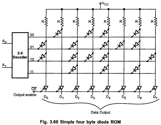
Diode ROM Memory consists of only diodes and a decoder. As shown in the Fig. 3.69 address lines A0 and A1 are decoded by 2 : 4 decoder and used to select one of the four rows. As decoder output is active low, it places a logic 0 on the selected row. Each output data line goes to logic 0 if a diode connects the output data column to the selected row. Data is available on the output data lines only when output enable (OE) signal is low.
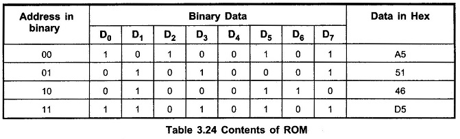
Table 3.24 shows the contents of ROM at four locations.
Now a days ROMs use MOS technology instead of diode. Fig. 3.70 shows four nibble (half-byte) ROM using MOS transistors. Here, diodes and pull up resistors are replaced by MOS transistors. The address on the address lines (A0 and A1) is decoded by 2 : 4 decoder. Decoder selects one of the four rows making it logic 0. The inverter connected at the output of decoder inverts the state of selected row (i.e. logic 1). Therefore, each output data line goes to logic 0 if a gate of MOS transistor is connected to row select lines. When gate of the MOS transistor is connected to the selected row, MOS transistor is turned on. This pulls the corresponding column data line to logic 0.
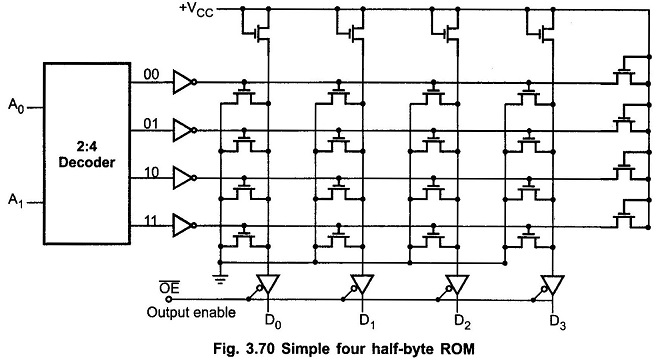
In integrated circuits, a thin metallized layer connects the gates of some transistors to the row select lines. The gate connections of MOS transistors depend on the data to be stored in the ROM Memory. Therefore, according to the user truth table, manufacturer can deposit thin layer of metal to connect gates of the transistors.
Once the pattern/mask is decided, it is possible to make thousands of such ROMs. Such ROMs are called Mask-programmed ROMs. Masked ROMs are used in microprocessor based toys ,TV games, home computers and other such high volume consumer products.