Probes for CRO:
Direct Probes (1 : 1):
The simplest types of Probes for CRO (one can hardly call it a probe) is the test lead. Test leads are simply convenient lengths of wire for connecting the CRO input to the point of observation. At the CRO end, they usually terminate with lugs, banana tips or other tips to fit the input jacks of the scope, and at the other end have a crocodile clip or any other convenient means for connection to the electronic circuit.
Since a CRO has high input impedance and high sensitivity, the test leads should be shielded to avoid hum pickup, unless the scope is connected to low impedance high level circuits.
Although the input impedances of most CROs are relatively very high compared to the circuits where they are connected, it is often desirable to increase their impedance to avoid loading of the circuits or causing unstable effects. Carbon
The input capacitance of the scope, plus the stray capacitance of the test leads, may be just enough to cause a sensitive circuit to break into oscillation when the CRO is connected. This effect can be prevented by an isolation probe made by placing a carbon resistor in series with the test lead, as shown in Fig. 7.44.
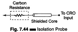
A slight reduction in the amplitude of the waveform and a slight change in the waveshape occurs with this probe. To avoid this possibility, a high impedance compensated probe, called a low capacitance probe or a 10 : 1 probe, is used.
Passive Voltage (High Z) Probe:
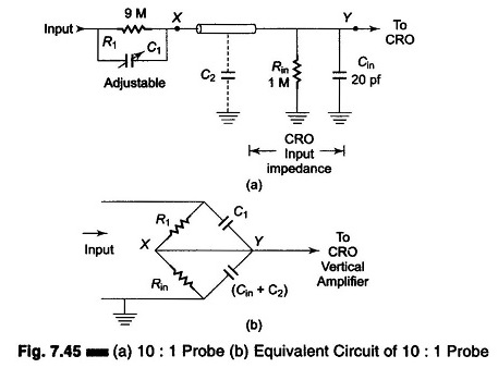
Figure 7.45 (a) shows a 10 : 1 probe. Figure 7.45 (b) shows the equivalent circuit. Referring to Fig. 7.45 (b). The capacitor is adjusted so that the elements of the bridge are balanced. Under conditions of balance we have
![]()
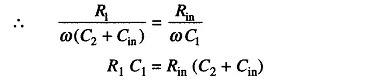
Therefore, X and Y are equipotential and the effect of the probe is equivalent to placing a potential divider consisting of R1 and Rin across the input circuit. The attenuation of the signal is 10 : 1, i.e. (R1 + Rin)/ R1 = 10 : 1 over a wide frequency range. Therefore, it is called a compensated 10 x 1 probe. As far as dc voltage inputs are concerned, the coaxial capacitance equals 30 pf per foot. (Assuming a coaxial length of 3.5 ft, the total coaxial length capacitance is 105 pf). Substituting this value in the balance bridge equation, we have
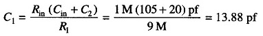
Therefore, the input capacitance of a CRO can range from 15-50 pf. C1 should be adjusted from 13-47 pf. It must be adjusted to obtain optimum frequency response from the probe-CRO combination. The C1 adjustment is done by connecting the probe tip to a square wave of 1 kHz and observing the CRT display. When the CRT display has optimum response, the C1 value is deemed to be appropriate.
Therefore

Active Probes:
Active probes are designed to provide an efficient method of coupling high frequency, fast rise time signals to the CRO input. Usually active probes have very high input impedance, with less attenuation than passive probes. Active devices may be diodes, FETs, BJTs, etc.
Active probes are more expensive and bulky than passive probes, but they are useful for small signal measurements, because their attenuation is less.
Active Probes Using FETs:
Figure 7.46 shows a basic circuit of an active probe using a FET.
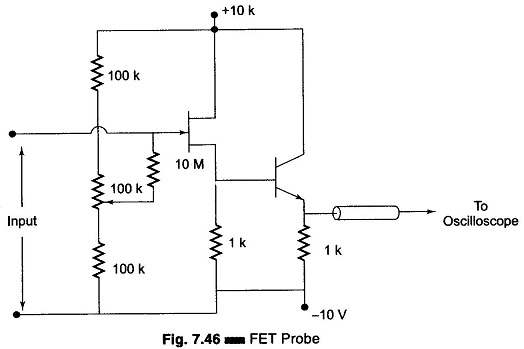
The FET is used as the active element to amplify the input signal. Although the voltage gain of the FET follower circuit shown is unity, the follower circuit provides a power gain so that the input impedance can be increased. To be effective the FET must be mounted directly in the voltage probe tip, so that the capacitance of the interconnecting cable can be eliminated. This requires that the power for the FET be supplied from the oscilloscope to the FET in the probe tip. The FET voltage follower drives a coaxial cable, but instead of the cable connecting directly to the high input impedance of the oscilloscope, it is terminated in its characteristic impedance.
There is no signal attenuation between the FET Amplifier and the probe tip. The range of the signals that can be handled by the FET probe is limited to the dynamic range of the FET amplifier and is typically less than a few volts. To handle a larger dynamic range, external attenuators are added at the probe tip. Active probes have limited use because the FET probe effectively becomes an FET attenuator. Therefore, oscilloscopes are typically used with a 10 to 1 attenuator probe.