Summing Integrator Circuit:
Many useful circuits can be designed using the basic integrator circuit. One of such useful circuits is the Summing Integrators. It can be obtained by applying more than one input to the basic integrator circuit. The Summing Integrator Circuit is shown in the Fig. 2.43.
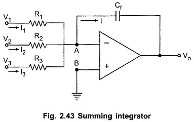
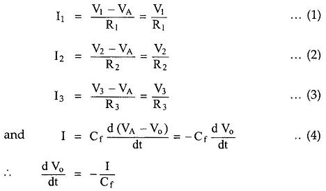
The node B is ground hence node A is at virtual ground i.e. VA = 0. Hence we can write for various currents,
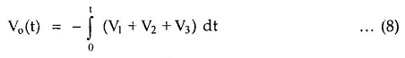
Integrating both sides,![]()
Applying KCL at node A,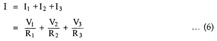
Substituting in (5),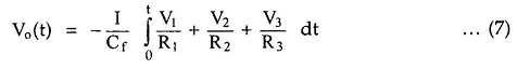
The expression shows that the output is the integration of the sum of the input voltages. Hence the circuit is called as summing integrators.
If R1 = R2 = R3 = R = 100 K and Cf = 10μF then we get,