IC Operational Amplifiers Articles:
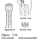
Discrete Transistor Packaging: Many low-power transistors are encapsuled in resin with protruding metal connecting leads, as illustrated in Fig. 7-24. This is known as a TO-92 package. Note the emitter, base, and collector terminal connections. These are … (Read More)
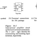
Integrated Circuit Operational Amplifier: Circuit Symbol and Packages – Figure 14-1(a) shows the triangular circuit symbol for an Integrated Circuit Operational Amplifier (op-amp). As illustrated, there are two input terminals, one output terminal, and two supply terminals. The inputs are identified … (Read More)
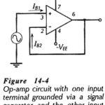
Biasing Bipolar Op Amp Circuit: Like other electronic devices, operational amplifiers must be correctly biased if they are to function properly. As already discussed, the inputs of an operational amplifier are the base terminals of … (Read More)
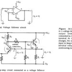
Voltage Follower Circuit Diagram: Direct-Coupled Voltage Follower – The IC operational amplifier can be employed for an infinite variety of applications. The very simplest application is the direct-coupled Voltage Follower Circuit Diagram shown in Fig: 14-10(a). The output terminal is connected … (Read More)
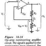
Non Inverting Amplifier Theory: Direct-Coupled Noninverting Amplifier – The Non Inverting Amplifier Theory circuit in Fig. 14-14 behaves similarly to a voltage follower circuit with one major difference. Instead of all of the output voltage being fed directly back to the … (Read More)
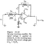
Direct Coupled Inverting Amplifier: The circuit in Fig. 14-18 is termed an Direct Coupled Inverting Amplifier because, with Vi applied via R1 to the inverting input terminal, the output goes negative when the input goes positive, and vice versa. Note that the noninverting … (Read More)
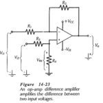
Differential Amplifier Circuit Operation: A Differential Amplifier Circuit Operation amplifies the difference between two inputs. The circuit shown in Fig. 14-23 is a combination of inverting and noninverting amplifiers. Resistors R1, R2, and the op-amp constitutes an inverting amplifier for a … (Read More)
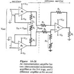
Instrumentation Amplifier Circuit Working: Circuit Operation – At first glance, the Instrumentation Amplifier Circuit Working in Fig. 14-28 looks complex, but when considered section by section it is found to be quite simple. First, note that the second stage (consisting of … (Read More)
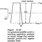
Voltage Level Detectors: Operational amplifiers are often used in circuits in which the output is switched between the positive and negative saturation voltages, +Vo(sat) and -+Vo(sat). The actual voltage change that occurs is known as the output voltage … (Read More)
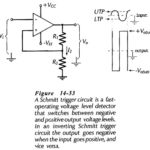
Schmitt Trigger Circuit Diagram: Inverting Schmitt Trigger – A Schmitt Trigger Circuit Diagram is a fast-operating voltage level detector. When the input voltage arrives at a level determined by the circuit components, the output voltage switches rapidly between its maximum positive … (Read More)