Forces in system with Permanent Magnets:
Method of finding Forces in system with Permanent Magnets is best illustrated by an example. Figure 4.17(b) shows a moving armature relay excited by a permanent magnet (PM).
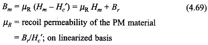
The dc magnetizing curve of the permanent magnet is drawn in Fig. 4.17(a) which upon linear extrapolation at the lower B-end can be expressed as
Soft iron portion of the magnetic circuit including the armature is assumed to have μ = ∞. For finding the force on the armature, it will be convenient to use Eq. (4.25) for which we will need the expression of system co-energy W′f (i, x) which must be independent of i as there is no exciting current in the system. Thus coenergy will be a function of the space variable x only i.e.,
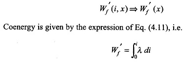
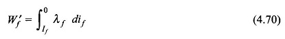
This expression needs to be carefully interpreted for the case of permanent magnetic excited systems. The limits of integration in this expression mean from state of zero flux to a state of certain flux (but with zero current). The state of zero flux is imagined by means of a fictitious exciting coil (of Nf turns) carrying current if as shown in
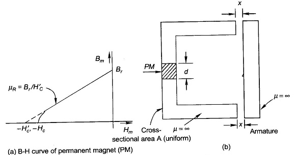
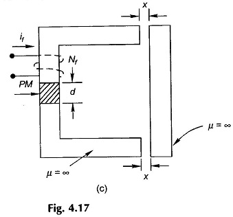
Fig. 4.17(c). The current is assumed to be adjusted to value If causing the core flux to reduce to zero and the original state is then reached by imaging the current (if) to reduce to zero. Thus
At any value of if, we can write
![]()
Continuity of flux allows us to wirte

Substituting for Hg in Eq. (4.71)
![]()
Substituting for Hm from Eq. (4.69) and solving we get
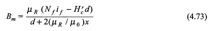
Flux linkages of the fictitious coil are given by
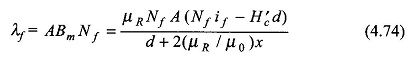
Flux and Flux linkages would be zero at
![]()
Substituting Eq. (4.70), we get
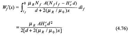
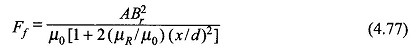
The force on the armature is then given by
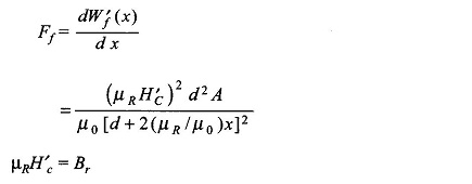
Therefore,
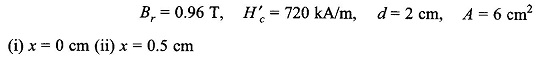
Let us now calculate the magnitude of the force for typical numerical values as below,
Now
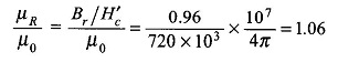
Substituting values in force equation (Eq. (4.77))
(i) x =0
![]()
(ii) x = 0.5 cm
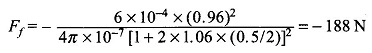
Note: Negative sign in force is indicative of the fact that the force acts in a direction to reduce x (air-gap).
Similar treatment could be used for mixed situation where system has both permanent magnets and exciting coils. It should be stressed here that an alternative procedure is to use the finite element method to evaluate the coenergy from the vector form of Eq. (4.18a) integrated over the volume, i.e.,
![]()
To calculate Forces in system with Permanent Magnets -dW′f/dx is obtained by numerical differentiation. This method is of general applicability wherever the magnetic circuit analysis cannot be carried out.