Electrostatic Voltmeters:
In Electrostatic Voltmeters fields, the attractive force between the electrodes of a parallel plate capacitor is given by
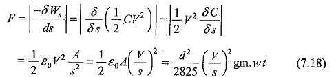
where,
V = applied voltage between plates,
C = capacitance between the plates,
A = area of cross-section of the plates,
d = diameter of plates
s = separation between the plates,
ε0 = permittivity of the medium (air or free space), and
Ws = work done in displacing a plate
When one of the electrodes is free to move, the force on the plate can be measured by controlling it by a spring or balancing it with a counter weight. For high voltage measurements, a small displacement of one of the electrodes by a fraction of a millimeter to a few millimeters is usually sufficient for voltage measurements. As the force is proportional to the square of the applied voltage, the measurement can be made for a.c. or d.c. voltages.
Electrostatic Voltmeters Construction:
Electrostatic voltmeters are made with parallel plate configuration using guard rings to avoid corona and field fringing at the edges. An absolute voltmeter is made by balancing the plate with a counter weight and is calibrated in terms of a small weight. Usually the electrostatic voltmeters have a small, capacitance (5 to 50 pF) and high insulation resistance (R ≥ 1013 Ω). Hence they are considered as devices with high input impedance. The upper frequency limit for a.c. applications is determined from the following considerations:
- natural frequency of the moving system,
- resonant frequency of the lead and stray inductances with meter capacitance, and
- the R-C behavior of the retaining or control spring (due to the frictional resistance and elastance).
An upper frequency limit of about one MHz is achieved in careful designs. The accuracy for a.c. voltage measurements is better than ± 0.25%, and for d.c. voltage measurements it may be ± 0.1% or less.
The schematic diagram of an absolute electrostatic voltmeter is shown. The moving electrode is surrounded by a fixed guard ring to make the field uniform in the central region. In order to measure the given voltage with precision, the disc diameter is to be increased, and the gap distance is to be made less. The limitation on the gap distance is the safe working stress ( V/s) allowed in air which is normally 5 kV/cm or less. The main difference between several forms of voltmeters lies in the manner in which the restoring force is obtained. For conventional versions of meters, a simple spring control is used, which actuates a pointer to move on the scale of the instruments. In more versatile instruments, only small movements of the moving electrodes is allowed, and the movement is amplified through optical means (lamp and scale arrangement as used with moving coil galvanometers).
Two air vane dampers are used to reduce vibrational tendencies in the moving system, and the elongation of the spring is kept minimum to avoid field disturbances. The range of the instrument is easily changed by changing the gap separation so that V/s or electric stress is the same for the maximum value in any range. Multi-range instruments are constructed for 600 kV rms and above.
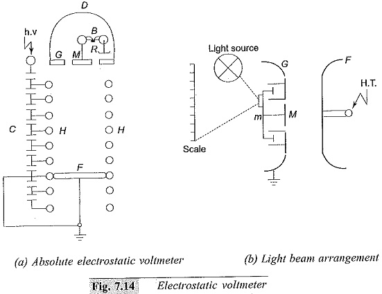
where
M – Mounting plate
G – Guard plate
F – Fixed plate
H – guard hoops or rings
m – mirror
B – Balance
C – Capacitance divider
D – Dome
R – Balancing weight
The constructional details of an absolute electrostatic voltmeter is given in disc M forms the central core of the guard ring G which is of the same diameter as the fixed plate F. The cap D encloses a sensitive balance B, one arm of which carries the suspension of the moving disc. The balance beam carries a mirror which reflects a beam of light.
The movement of the disc is thereby magnified. As the spacing between the two electrodes is large, the uniformity of the electric field is maintained by the guard rings fl which surround the space between the discs F and M. The guard rings H are maintained at a constant potential in space by a capacitance divider ensuring a uniform special potential distribution.
Some instruments are constructed in an enclosed structure containing compressed air, carbon dioxide, or nitrogen. The gas pressure may be of the order of 15 atm. Working stresses as high as 100 kV/cm may be used in an electrostatic meter in vacuum. With compressed gas or vacuum as medium, the meter is compact and much smaller in size.