Phase Margin Optimum
Phase Margin Optimum: The method can be based on the phase margin in which the controller is designed to provide a minimum phase margin. The design makes use of Bode…
Continue Reading
Phase Margin Optimum
Phase Margin Optimum: The method can be based on the phase margin in which the controller is designed to provide a minimum phase margin. The design makes use of Bode…
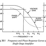
Single Stage Amplifier Frequency Response and Phase Response Curves: The voltage gain of a single-stage transistor amplifier commences to fall off at some high frequency. This fall-off may be due…
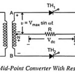
Single Phase Full Wave Controlled Rectifier (or Converter): In case of Single Phase Full Wave Controlled Rectifier (or Converter) both positive and negative halves of ac supply are used and,…
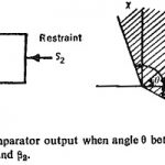
Phase Comparator Circuit: Phase Comparator Circuit technique is the most widely used for all practical directional, distance, differential and carrier relays. If the two input signals are S1 and S2…
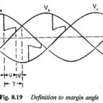
Margin Angle Control of Synchronous Motors: The commutation Margin Angle Control of Synchronous Motors is defined as the angle measured from the end of commutation to the crossing of the…
Frequency Domain Analysis in Network Analysis Articles: Frequency Domain Analysis: As we now already, the responses of the networks to the various time dependent inputs such as step, ramp, exponential…
Specification from Bode Plot: The important Specification from Bode Plot are, Gain cross-over frequency (ωgc) Phase cross-over frequency (ωpc) Gain margin (G.M.) Phase margin (P.M.) Gain Cross-over Frequency (ωgc): The…
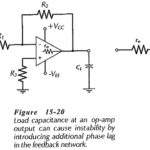
Load Capacitance Effect: Capacitance connected at the output of an operational amplifier is termed Load Capacitance Effect (CL). Figure 15-20 shows that CL is in series with the op-amp output resistance…