Transistor Buffer Circuit
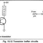
Transistor Buffer Circuit: The Fig. 15.12 shows the Transistor Buffer Circuit. In these Transistor Buffer Circuit, transistor is used as a switch. It can be switch ON or OFF with…
Emitter Follower Circuit - Operation, Advantages and Applications: Emitter Follower Circuit is also a negative current feedback circuit. This circuits exhibits a large input impedance, a small output impedance, and…
OTA in Sample and Hold Circuits: The OTA can be used in sample and hold circuits, as shown in Fig. 41.15. To sample and hold the input signal the control…
Common Drain Amplifier Circuit Diagram: The FET Common Drain Amplifier Circuit Diagram shown in Fig. 11-14 has the output voltage developed across the source resistor (RS). The external load (RL)…
Common Collector Circuit Analysis: In the Common Collector Circuit Analysis (CC) shown in Fig. 6-28 the external load (RL) is capacitor-coupled to the transistor emitter terminal. The circuit uses voltage divider…
Sample and Hold Circuit: Four basic sample and hold circuit are shown in Fig. 14.141. In these circuits a JFET is used as switch. During the sampling time the JFET…
Applications in Circuit Breaker: Applications in Circuit Breaker : A circuit breaker is a switch which automatically interrupts the circuit when a critical current or voltage rating is exceeded. A.c.…
Instrumentation Amplifier Circuit: The schematic diagram of an Instrumentation Amplifier Circuit constructed with dc opamps and consisting of general features is shown in Fig. 14.23 (a). Many of the input…