Tap Changing Transformers:
The excitation control method is satisfactory only for relatively short lines. However, it is not suitable for long lines as the voltage at the alternator terminals will have to be varied too much in order that the voltage at the far end of the line may be constant. Under such situations, the problem of voltage control can be solved by employing other methods. One important method is to use Tap Changing Transformers and is commonly employed where main transformer is necessary. In this method, a number of tapping are provided on the secondary of the transformer. The voltage drop in the line is supplied by changing the secondary e.m.f. of the transformer through the adjustment of its number of turns.
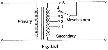
1. Off Load Tap Changing Transformer: Fig. 15.4 shows the arrangement where a number of tapping have been provided on the secondary. As the position of the tap is varied, the effective number of secondary turns is varied and hence the output voltage of the secondary can be changed. Thus referring to Fig. 15.4, when the movable arm makes contact with stud 1, the secondary voltage is minimum and when with stud 5, it is maximum. During the period of light load, the voltage across the primary is not much below the alternator voltage and the movable arm is placed on stud 1. When the load increases, the voltage across the primary, drops, but the secondary voltage can be kept at the previous value by placing the movable arm on to a higher stud. Whenever a tapping is to be changed in this type of transformer, the load is kept off and hence the name off load Tap Changing Transformers.
The principal disadvantage of the circuit arrangement shown in Fig. 15.4 is that it cannot be used for tap-changing on load. Suppose for a moment that tapping is changed from position 1 to position 2 when the transformer is supplying load. If contact with stud 1 is broken before contact with stud 2 is made, there is break in the circuit and arcing results. On the other hand, if contact with stud 2 is made before contact with stud 1 is broken, the coils connected between these two tappings are short-circuited and carry damaging heavy currents. For this reason, the above circuit arrangement cannot be used for tap-changing on load.
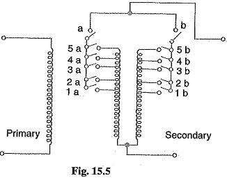
2. On Load Tap Changing Transformer: In supply system, tap-changing has normally to be performed on load so that there is no interruption to supply. Fig. 15.5 shows diagrammatically one type of on-load Tap Changing Transformers. The secondary consists of two equal parallel winding which have similar tapping 1a….5a and 1b….5b. In the normal working conditions, switches a, b and tapping with the same number remain closed and each secondary winding carries one-half of the total current. Referring to Fig. 15.5, the secondary voltage will be maximum when switches a, b and 5a, 5b are closed. However, the secondary voltage will be minimum when switches a, b and primary Secondary 1a, 1b are closed.
Suppose that the transformer is working with tapping position at 4a, 4b and it is desired to alter its position to 5a, 5b. For this purpose, one of the switches a and b, say a, is opened. This takes the secondary winding controlled by switch a out of the circuit. Now, the secondary winding controlled by switch b carries the total current which is twice its rated capacity. Then the tapping on the disconnected winding is changed to 5a and switch a is closed. After this, switch b is opened to disconnect its winding, tapping position on this winding is changed to 5b and then switch b is closed. In this way, tapping position is changed without interrupting the supply. This method has the following disadvantages :
- During switching, the impedance of transformer is increased and there will be a voltage surge
- There are twice as many tappings as the voltage steps.