Digital to Analog Converter Circuit Diagram
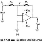
Digital to Analog Converter Circuit Diagram: The basic Digital to Analog Converter Circuit Diagram using Op Amp is shown in Fig. 17.18(a). The input signal is applied to the inverting…
Ladder Type Converter D/A: Looking into any load from the left side we always see a resistor R. Similarly looking from the right side for any load, one always sees…
Self Oscillating Converter (Transistorized Chopper Circuit): Self Oscillating Converter (Transistorized Chopper Circuit) - A Transistorized dc to ac converter suitable for low level dc signal is illustrated in Fig. 14.30.…
Principle Operation of Switching Power Converters: Controllable reactive power can be generated by dc to ac switching converters which are switched in synchronism with the line voltage with which the…
Three Phase Semi Converter feeding Separately Excited DC Motor: Large-kW motors are fed from 3-phase supply through three Phase Converters. In a three Phase Semi Converter, the ripple frequency of…
DC Motor Control through Converters: DC motor control is conveniently and efficiently achieved by phase-controlled converters wherein the ac input voltage is converted to a controlled dc output. The commutation…
Types of Converters in Power Electronics: The different types of converters in power electronics are AC/DC Converters AC/AC Converters The Matrix Converter DC/DC Converters DC/AC Converters Control VSI Current Source…
What is Power Electronic Converter?: What is Power Electronic Converter? - Since the introduction of the thyristor, the Power Electronic Converter technology has progressed through intense technological evolution for the…