Fuel Handling System and Ash Handling System:
Handling of coal:
The coal handling is divided into two types:
- Out-plant handling.
- In-plant handling.
1. Out-plant handling:
This handling includes the handling of coal from coal mine to the thermal power plant. These handlings are done outside the plant in the following ways.
(a) Transportation by sea or river:
If the power plant is located on the bank of river (or) near sea shore, then it is most economical to transport the coal by ships. The coal is unloaded from the ship and taken to the plant through desired handling methods.
(b) Transportation by rail:
The most commonly used means of transportation of coal is by rail. A railway sliding line is taken to the power station and the coal is either delivered to the point of consumption or to the storage yard.
(c) Transportation by Road:
This type of coal transportation is used only for small capacity plants. In this the coal is carried upto the point of consumption of the power plant. It is the major advantage in this kind of transportation. Self-tripping lorries are used for transporting the coal and the lorries have one (or) two hydraulic cylinder to unload coal from the lorries after it has been weighed.
(d) Transportation of coal by pipeline:
In this type, the coal is transported through pipeline.
The advantages and disadvantages are listed below.
Advantages:
- It is unaffected by weather and climate and it is continuous transport system.
- It has high degree of reliability and safety since the moving parts are limited.
- Transportations are made in large quantities
- Maintenance and man power requirements are low.
- Transportation losses are eliminated.
- It is more economical while dealing with large volume of coal over long distance.
Disadvantages:
- High capital is required for preparation of coal at pumping station as well as dewatering and recovery of coal.
- Water requirement is high as the water coal ratio in the mixture is 1:1.
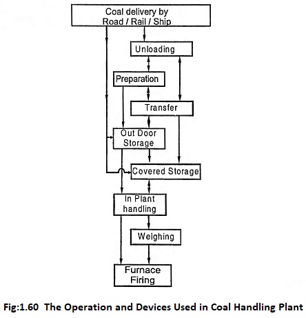
2. Inplant handling of coal:
In order to handle large quantity of coal inside the plant, some mechanical handling systems are provided for smooth, easy and better controlled operation.
The following are to be considered while designing the inplant coal handling.
- Implant transportation should be minimum and should be simple and sound.
- There should not be rehandling of coal.
- For better maintenance and inspection, the handling units should be centralized.
- The prime-movers used should be of electrical motors of high residual value.
- To avoid corrosion and abrasion, the working parts should be enclosed.
- It should be capable of delivering coal at peak hours.
The implant coal handling is divided into following categories
- Coal unloading
- Coal preparation
- Coal storage
- Coal transfer
(a) Coal unloading:
The kind of unloading equipment used is based on the out plant handling. For small and medium capacity plants, transportation of coal by trucks is more economical. Lift trucks with scoops are used because these trucks can unload without additional equipment’s. Generally rail transport is used when large quantities of coal is to be transmitted for long distances. The transported coal are unloaded into the unloading hoppers or directly to coal conveyors. For the fastest unloading, the following are used: Car shakers, rotary car dampers, coal accelerators, unloading towers and bridges, self-unloading boats, lift trucks, cranes and buckets. The coal towers, unloading bridges and self unloading boats are used when the coal is transmitted by sea.
(b) Coal preparation:
The coal from coal mines can not be directly fed into the furnace. Proper preparation on the coal should be done before feeding the coal to the furnace. In the coal preparation, the coal has to pass through the following equipment’s. 1. Crushers 2. Sizers 3. Driers and 4. Magnetic separators.
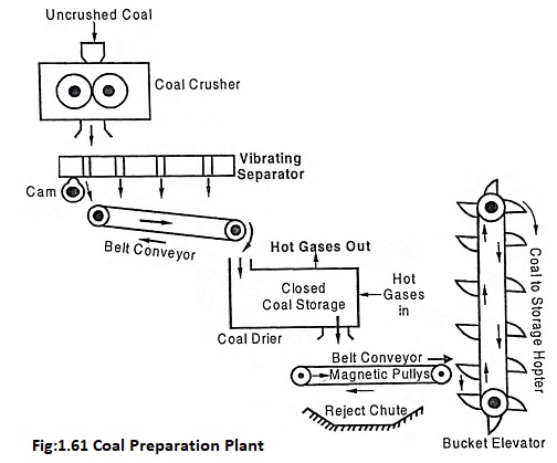
The coal to be supplied to the combustion chamber should be of proper size. So this crushers are necessary to crush the raw coal to the required size. The crushers capacity is 600 tons per hour in order to meet peak load requirements. The crushed coal is passed through the sizer where unsized coal is separated and sent back to the crushers. In the drier, the sized coal is dried to remove the moisture in the coal. The hot flue gases are passed through the coal storage in closed space for removing the moisture from coal. The iron scrap and other particles are removed with the help of magnetic separators because these iron scrap may chock the burners and may increase the wearing of the handling equipment. Usually, the separator consists of magnetized pulley. When the coal is passed over the pulley, the iron particles cling to the belt. The iron particles drop off into a reject chute as they leaves the pulley.
(c) Coal storage:
The crushed coals are stored here, ready for transfer.
(d) Coal Transfer:
The coal transfer starts by carrying of coal from unloading point to the storage site. The different types of coal transforming equipments are given below.
- Belt conveyors, 2. Screw conveyors, 3. Bucket elevators, 4. Grab bucket elevators, 5. Skip hoists and 6. Flight conveyors.
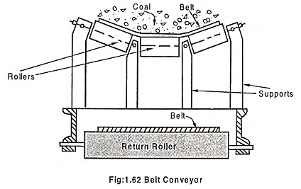
1. Belt conveyors:
Belt conveyors are suitable for transporting coal over long distance with large quantity. The arrangement of belt conveyor is shown in the Fig.1.62. An endless belt made of rubber, canvass or balata is made to run over a pair of end drums and pulleys and supported by series of roller at regular intervals. The conveyors can have inclination of 20° to the horizontal. The load carrying capacity is 50 to 100 tonnes per hour. The speed of the conveyor varies from 60m to 100m per hour.
Advantages:
- Most economical for medium and large plants.
- By increasing the speed of belt, rate of transfer can be increased.
- Minimum maintenance and repair cost.
- Lesser power consumption compared to other means.
- Coal is protected from rain and wind just by providing overhead covers.
Disadvantage:
- Not suitable for short distance.
- Not suitable for greater heights, since the inclination is limited to 20° to horizontal.
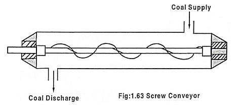
2. Screw conveyor:
The line diagram of screw conveyor is shown in Fig.1.63. An endless helicoid screw is fitted to the shaft. On one end of the shaft, the driving mechanism is fitted and the other end of shaft is supported on a ball bearing. While the screw is rotating, the coal is transferred from one end to the other end. The speed varies from 70 to 120 rpm and diameter of screw varies from 15cm to 50cm. The maximum capacity of this conveyor is 125 tonnes per hour.
Advantages:
- Space requirement is less and initial cost is low.
- It is simple and can be made dust tight.
- It is more compact.
Disadvantages:
- Power consumption is more.
- Wear and tear is high and hence life is less compared to belt conveyor.
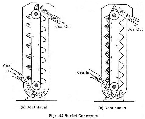
3. Bucket elevators:
The two types of bucket conveyors are shown in Fig.1.64. These conveyors are used for vertical lifts. In this, the buckets are fixed to a chain which moves over two wheels. The coal is loaded at bottom and unloaded at the top. The continuous type elevator carries more coal than the centrifugal type. The maximum height and inclination to the horizontal are 30.5 m and 60° respectively. The speed of centrifugal and continuous bucket conveyors are 75m/min and 35m/min respectively for about 60 tonnes capacity per hour.
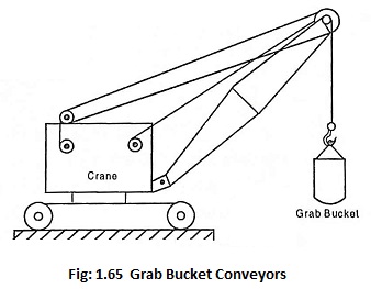
4. Grab Bucket Conveyor:
Grab bucket conveyor does both lifting and transferring of coal from one point to another. A bucket operating over a distance of 60m transfers nearly 100 tonnes of coal per hour. It’s initial cost is high but operating cost is low.
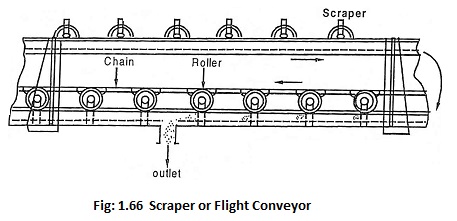
5. Scraper (or) Flight conveyor:
This conveyor is used for transferring of coal and filling number of storage bins situated under the conveyor. It has one or two strands of chain, to which steel scrapers are attached. The scraper scraps the coal through a trough and then it is discharged in the bottom of the trough as shown in Fig.1.66.
Advantages:
- It requires less space.
- In order to suit the requirements, the speed of the conveyor can be controlled.
- Coal handling as well as ash handling system can be done by using this flight conveyor.
Disadvantages:
- The conveyor life is short because there is a scrapping action resulting in excessive wear and tear.
- High maintenance cost.
- High speed cannot be allowed in order to reduce the abrasive action of the material handled.
- Power consumption is more due to dragging action.
Ash handling and dust collecting system:
A general layout of ash handling system and dust collecting system is shown in Fig.1.67.
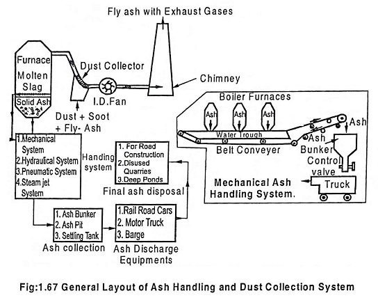
Ash handling system is classified into four groups.
- Mechanical handling system.
- Hydraulic system.
- Pneumatic system.
- Steam jet system.
Ash handling system is needed
- To remove the ashes from the furnace ash hopper.
- To convey the ashes from furnace ash-hopper to a storage.
- To dispose the ashes from the storage.
1. Mechanical handling system:
This system is used for low capacity power plants. The hot ash from the furnace falls on the belt conveyor and it is continuously carried to the overhead bunker or dumping site. With the help of trucks, the ash is carried from ash bunker to dumping site. The control valve is used to load the trucks, manually. The maximum capacity of this plant is 5 tons per hr. It has low power consumption.
2. Hydraulic ash handling system:
In this system, the ash is carried by the water with high velocity through a channel and dumped fully to the sump. This system is classified into two types: 1. Low velocity system (low pressure), 2. High velocity (high pressure) system.
(a) Low velocity system (Low pressure system):
The ash from the grate is made to fall into the system of water at lower velocity and it is carried to the sump with water.
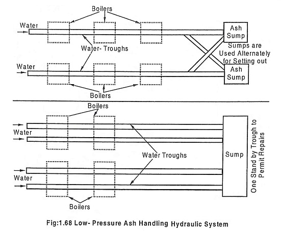
The velocity of water in trough is between 3 to 5 m/sec. The ash and water are separated when it reaches to the sump. The separated water is again used for the same and the ash collected in the sump is sent out through carriages. The ash carrying capacity is 50 tons/hr and distance covered is 500 mts.
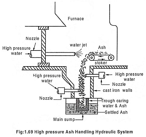
(b) High velocity system (high pressure system):
In this, the water nozzles are fitted at the top and on the sides of the hoppers below the boiler. The top nozzle is used to quench the ash and the side nozzles are provided to carry the ash through trough. The ash with high velocity is sent to the sump by trough. Water is separated and recirculated. The ash carrying capacity is 120 tonnes and distance covered is 1000 mts. The troughs and sumps are made of corrosion and wear resistant materials. This system can also be used for pulverized fuel plants.
Advantages:
- Most suitable for higher capacity thermal power plants since its ash carrying capacity is large.
- It can be handled easily with steam of molten ash.
- It can discharge the ash for long distance from plant.
- The whole system is clean, dustless and totally enclosed.
- Absence of working parts in contact with ash is the most important feature of this system.
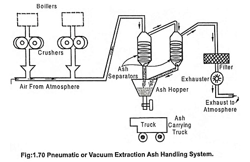
3. Pneumatic ash handling system:
This has been designed in such a way that it can handle abrasive ash and fine dust materials i.e., fly ash and soot. The high velocity of air stream, created by an exchauster at the discharge end, carries the ash and dust from discharge point. Ash from ash hopper is passed through the ash crushers into air stream. The ash is separated in two stages i.e. separated in the primary and secondary cyclone separators and the ashes are collected in the hopper. The separated clean air is exhausted to the atmosphere through filters. The power requirement of an exhauster is 5.H.P per ton (approx) of material.
Advantages:
- Dustless operation is possible as the materials are handled totally in an enclosed conduit.
- There is no freezing or sticking in the storage bins as the ash is conveyed in a dry state.
- Cost of the ash removal system is less than that of other system.
- There is no rehandling and spillage.
- The system has greater flexibility.
Disadvantages:
- Pipe lines wear out quickly.
- Maintenance cost is high.
- It is noisy operation than other types.
- Blockage of pipe line.
4. Steam jet system:
In this, a steam jet is used to carry dry solid materials of considerable size along with it. In this system, the direction of steam and ash travel are same. The ash is deposited in the ash hopper.
Advantages:
- Ash removal is economical for a horizontal distance of 200 meters and vertical distance of 30 metres.
- Capital cost is less.
- It can be positioned in backward position.
- It requires less space.
Disadvantages:
- Greater wear in pipe line by ash.
- System operation is noisy.
- Capacity of the system is limited to 15 tons per hour.
5. Dust collector: Mechanical Dust Collectors:
(a) Gravitational separators:
Three different types of dust separators are shown in Fig. 1.71. (a), (b) and (c). The arrangement shown in Fig 1.71(a) has the increasing cross sectional area. When the dust laden gases are passed at high velocity at the increasing cross section, the velocity is reduced and the dust particles falls down.
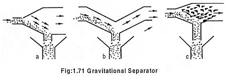
In the arrangement shown in Fig. 1.71 (b), the direction of flow of the gas is suddenly changed. By this, the heavier particles settle down quickly.
The arrangement shown in Fig. 1.71(c) has baffles. When the gas passed over this, the dust particles are knocked out and settles down.
(b) Bag house dust collector:
When low sulphur content coal and higher efficiency of the dust collection is required, fabric filters are used as an alternative to electrostatic precipitator.
The flue gas is sent inside the bags, then through the cloth into the house and then out. To avoid excess fabric friction, reverse flow of air is periodically supplied to clean the bag. Bag house dust collector has an efficiency of 99.9% and the efficiency is independent of amount of dust in the flue gas. It requires more maintenance. H2SO4 is formed when SO3 combines with water vapour. The flue gas temperature should be maintained at a temperature above dew point temperature of sulphuric acid in order to avoid its attack on the system. Dew point temperature of acid varies from 60°C to 170°C.
There are three types of bag house filters, as given below.
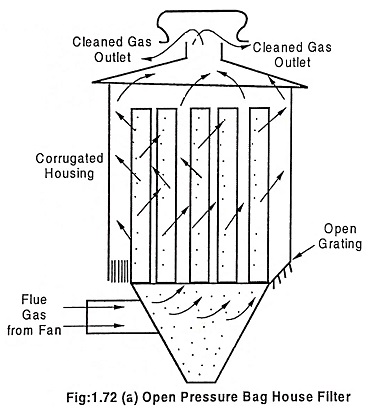
(i) Open pressure type:
Fig. 1.72(a) shows this arrangement, In this, the fan is located on the dust loaded side and it can be operated with open sides, with the protection provided from weather. It is constructed with corrugated steel (or) asbestos cement sheets. It can have open grating at the cell plate level and no hopper insulation is required.
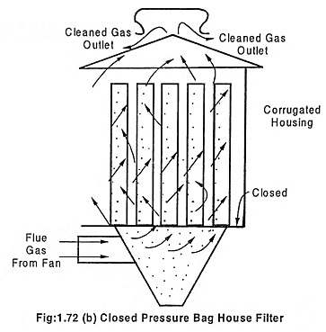
(ii) Closed pressure types:
It is used for gases having high Dew point temperature. The arrangement is shown in Fig. 1.72 (b). It is an air tight system and fan is located to inlet side of bag house similar to open system. The structure walls and hopper are insulated and the floor of the unit is closed.
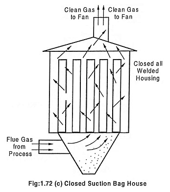
(iii) Closed suction type:
The arrangement is shown in Fig. 1.72 (c). It is same as that of closed pressure type but in this, the fan is located at the outlet of bag house clean gas side. In this, the floor, walls and hopper are insulated. It is suitable for gases having dew point temperature ranging 75°C to 85°C.
Advantages of the baghouse filters:
- Its efficiency remains constant irrespective of gas resistivity because cleaning mechanism is not electrostatic in nature as an electrostatic precipitator.
- It has high collection efficiency usually more than 9.99%.
- Cheaper than the electrostatic precipitators.
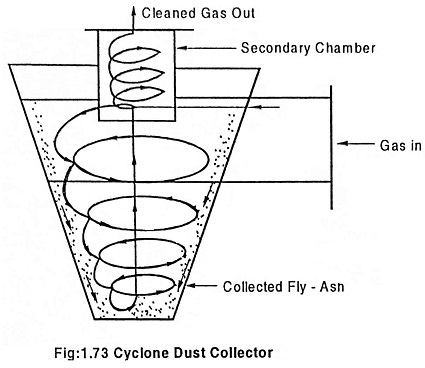
6. Cyclone Separators (Cyclone dust collector):
The high velocity flue gas with dust particles enter tangentially into a conical shell with high velocity. A whirling motion is imparted to the gas within the shell. By this, the heavier dust particles are thrown to the sides of shell the dust particles fallen down and is collected in the dust collector. The gas is then passed through the secondary chamber where dust particles, if any, are separated. Now the clean gas comes out of the chamber. This is most suitable for pulverised fuel firing units.