Complex Impedance

Parallel Circuits Definition

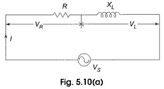
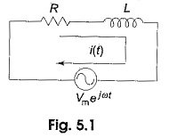
Parallel Circuits Definition: Parallel Circuits Definition – The complex number system simplifies the analysis of parallel ac circuits. In series circuits, the current is the same in all parts of the series circuit. In parallel ac circuits, the voltage is the same across each element. Parallel RC Circuits: The voltages for an RC series circuit […]

Parallel Circuits Definition Read More »

Series Circuit

Series Circuit: Series Circuit – The impedance diagram is a useful tool for analyzing series ac circuits. Basically we can divide the series circuits as RL, RC and RLC circuits. In the analysis of series ac circuits, one must draw the impedance diagram. Although the impedance diagram usually is not drawn to scale, it does

Series Circuit Read More »

Phasor Diagram Sine Wave

Phasor Diagram Sine Wave: A phasor diagram can be used to represent a sine wave in terms of its magnitude and angular position. Examples of Phasor Diagram Sine Wave are shown in Fig. 5.5. In Fig. 5.5(a), the length of the arrow represents the magnitude of the sine wave; angle θ represents the angular position

Phasor Diagram Sine Wave Read More »

Impedance Diagram

Impedance Diagram: Impedance Diagram is a complex quantity having real and imaginary parts; where the real part is the resistance and the imaginary part is the reactance of the circuit. Consider the RL series circuit shown in Fig. 5.1. If we apply the real function  Vm cos ωt to the circuit, the response may be Im

Impedance Diagram Read More »

Scroll to Top