Bolometer:
Bolometric measurements are based on the dissipation of RF power in a small temperature sensitive resistive element, called a Bolometer. This bolometer may be a short ultra thin wire having a positive temperature coefficient (PTC) of resistance, called Baretter, or a bead of semi-conductor having a negative temperature coefficient (NTC) called Thermistor.
Both Baretters and Thermistors can measure small powers, of the order of a fraction of micro-watts. They can also indicate or monitor large amounts of power by inserting a directional coupler.
The RF power to be measured heats the bolometer and causes a change in its electrical resistance, which serves as an indication of the magnitude of power.
The bolometer is generally used in a bridge network so that small changes in resistance can be easily detected and hence power can be measured.
Bolometer Method of Power Measurement
Bolometric measurements are based on the dissipation of RF power in a small, temperature sensitive resistive element, known as a bolometer. This may be a short ultra thin wire, a bead of semiconductor material or a thin conducting film of small dimensions.
The bolometer is generally incorporated into a bridge network, so that small changes in resistance can be readily detected and the power measurement performed by substitution of low frequency power.
In one procedure, the bridge is initially balanced with low frequency (or bias) power. (Power, for “the purpose of controlling or biasing bolometer resistance and bridge operating conditions is termed bias power.)
When RF power is applied to bolometer, low frequency power is withdrawn until the bridge is balanced again.
In any case, whatever the bridge technique used, the underlying assumption of the measurement is that equal amount of low frequency and RF power produce the same heating effect and resistance changes in the bolometer.
Bolometric measurement are well suited to the measurement of low and medium power, ranging from a few μ watts to a fraction of a μ watt.
Bolometer Element
In order that a bolometer element be well matched to the RF line, be equally responsive to low frequency and RF power, and be highly sensitive, it must be small in size.
In most bolometer elements, cross-sectional diameters are usually of the order of the skin depth of penetration of RF current at the highest frequency of operation. The dc and RF resistivities are essentially the same and the reactive component of the bolometer impedance is held to a minimum. The maximum cross-sectional area that can be tolerated is inversely proportional to the conductivity of the bolometer material and the highest frequency of operation. This explains why ultra thin metallic wires are required at micro wave frequency.
Metal wire bolometers are referred to as barreters. They have a positive temperature coefficient of resistance and are generally operated at bias powers which heat to 100 — 200°C. (They consist of short lengths of Wollaston wire whose external silver sheath has been removed by etching or deplating, so as to expose the extremely thin noble metal core, usually consisting of platinum or platinum alloy. Wire diameters range from approximately 1 — 3 microns and wire lengths range from as short as feasible to about 2.5 mm The resistance of the deplated portion is selected so that the bolometer presents a good match to the RF line when properly biased with low power.)
Since the dc and RF resistances are nearly the same, the resistance value is generally close to the characteristic impedance.
Thermistor elements for RF measurements are usually minute beads of a ceramic like semiconductor mixture of metallic oxides having a large negative temperature coefficient of resistivity.
Two fine platinum or platinum alloy wires are embedded in the bead, which is then sintered and coated with a film of glass. The beads are sometimes enclosed in a glass envelope.
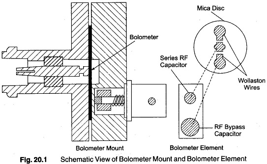
Bolometer Mount
The bolometer support consists of a thin mica disc on one side of which silver electrodes are sprayed. Silver painted holes through the mica connect the (lower) outer electrode to a circular electrode on the opposite side. Between the centre and outer electrodes are mounted two short (1 mm) lengths of deplated Wollaston wires of 1 micron diameter, each measuring 100Ω at dc with normal bias power. The mica disc is clamped in the holder, as shown in Fig. 20.1, so that the upper electrode makes contact with the metal case, while the other two electrodes are insulated from a co-axial line by a thin mica sheet which provides the bypass capacitor necessary to complete the RF circuit, and to place two wires in RF parallel across the line.
Measurement of Power by Means of a Bolometer Bridge
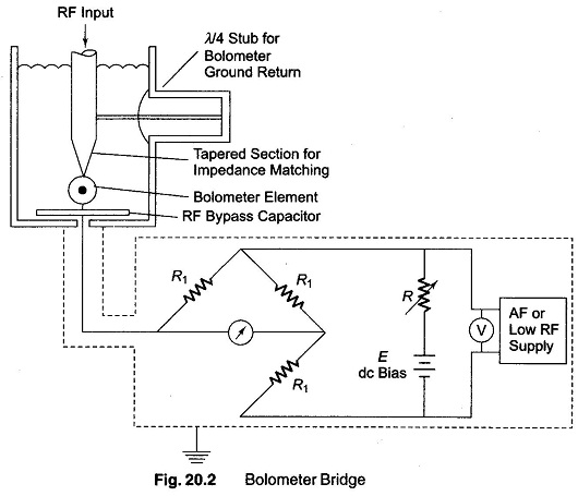
To measure unknown RF power, a small known AF power, indicated by the voltmeter V1, is superimposed on the RF test power. The direct current from voltage E is next adjusted by varying R, which heats the bolometer element until its resistance equals R1, which is the value required to balance the bridge. The test RF power is then turned off, which unbalances the bridge. Balance is now restored by increasing the AF voltage to V2. Hence RF power equals.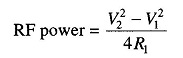
Since power delivered to the bolometer element is 1/4th power given to the bridge.
In a co-axial and wave guide transmission system, the bolometer mount must provide the necessary impedance transformation (matching). In a co-axial cable, a 50Ω transmission line impedance has to be transformed to a 125 —200Ω resistance value of a bolometer. This is usually done by means of a tapered section, as shown in Fig. 20.2.
Unbalanced Bolometer Bridge
An unbalanced bolometer bridge is shown in Fig. 20.3. In the absence of RF power, the bridge is brought into balance by adjusting the exciting source voltage. The detector now indicates the balance condition of zero. The test RF is now applied to the bolometer element. The resistance of the bolometer changes, and the bridge is unbalanced by an amount indicated by the detector, which gives the magnitude of RF power directly.
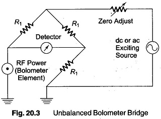
The unbalanced bridge method is probably the simplest means of realising a direct reading bridge and is particularly suited for low power measurement. The disadvantage is that the impedance of the bolometer changes (because the resistance of the bolometer is a function of RF power level), thereby upsetting the impedance match to the RF system. The advantage is that the bridge gives a direct reading.
One method of calibration is to note the detector deflections corresponding to a series of different RF power inputs, each of which is separately determined by rebalancing the bridge and measuring the equivalent bias power (that must be retracted).
Another method, which is not accurate, is to calibrate only the largest deflection that is used and rely on the linear performance for intermediate positions.
Self Balancing Bolometer Bridge
The term self balancing is used to describe bridges which are automatically rebalanced when unknown RF power is applied to the bolometer. A typical circuit is illustrated in Fig. 20.4.
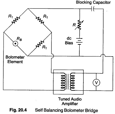
The bolometer bridge is used as the coupling network between the output and input of a high gain frequency selective audio amplifier. The feedback is in proper phase to produce sustained AF oscillations of such amplitude as well maintain the resistance of the bolometer at the fixed value which nearly balances the bridge.
When the supply is switched ON, the bridge is unbalanced. The gain of the amplifier is large, so that oscillations are allowed to build up until the bridge is almost balanced. The higher the gain of the amplifier, the more closely the bridge balances.
The test RF is now dissipated into the bolometer element, which causes an imbalance in the bridge circuit. The AF output voltage automatically aajusts itself to restore the bolometer resistance to its original value. The amount by which the AF power level in the bolometer is reduced equals the applied RF power. The voltmeter reads the AF voltage and can be calibrated to read the magnitude of RF power directly.
A typical bridge circuit offers seven power ranges, from 0.1 — 100 mW full scale, for use with bolometers having a resistance within + 10% of five selected values from 50 — 250 Ω.