8051 Interrupts:
The 8051 Interrupts provides 5 interrupt sources. The 8052 provides 6. These are shown in Fig. 12.28.
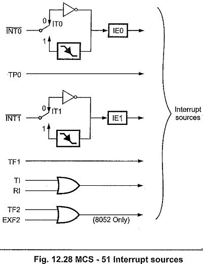
The external Interrupts INT0 and INT1 can each- be either level-activated or transition-activated, depending on bits IT0 and IT1 in Register TCON. The flags that actually generate these interrupts are bits IE0 and -IE1 in TCON. When an external interrupt is generated, the flag that generated it is cleared by the hardware when the service routine is vectored to only if the interrupt was transition-activated. If the interrupt was level-activated, then the external requesting source is what controls the request flag, rather that the on-chip hardware.
The Timer 0 and Timer 1 Interrupts are generated by TF0 and TF1, which are set by a rollover in their respective Timer/Counter registers (except see Timer 0 in Mode 3). When a timer interrupt is generated, the flag that generated it is cleared by the on-chip hardware when the service routine is vectored to.
The Serial port Interrupt is generated by the logical OR of RI and TI. Neither of these flags is cleared by hardware when the service routine is vectored to. In fact, the service routine- will normally have to determine whether it was RI or TI that generated the . interrupt, and the bit will have to be cleared in software.
In the 8052, the Timer 2 Interrupt is generated by the logical OR of TF2 and EXF2. Neither of these flags is cleared by hardware when the service routine is vectored to. In fact, the service routine may have to determine whether it was TF2 or EXF2 that generated, the interrupt, and the bit will have to be cleared in software.
All of the bits that generate interrupts can be set or cleared by software, with the same result as though it had been set or cleared by hardware. That is, interrupts can be generated or pending interrupts can be canceled in software.
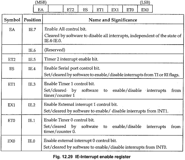
Each of these interrupt sources can be individually enabled or disabled by setting or clearing a bit in special Function Register IE (Fig. 12.29) . IE contains also a global disable bit, EA, which disables all interrupts at once.
Note in Fig. 12.29 that bit position IE.6 is unimplemented. In the 8051 Interrupts, bit position IE.5 is also unimplemented. User software should not write is to these bit positions, since they may be used in future MCS-51 products.
Priority Level Structure:
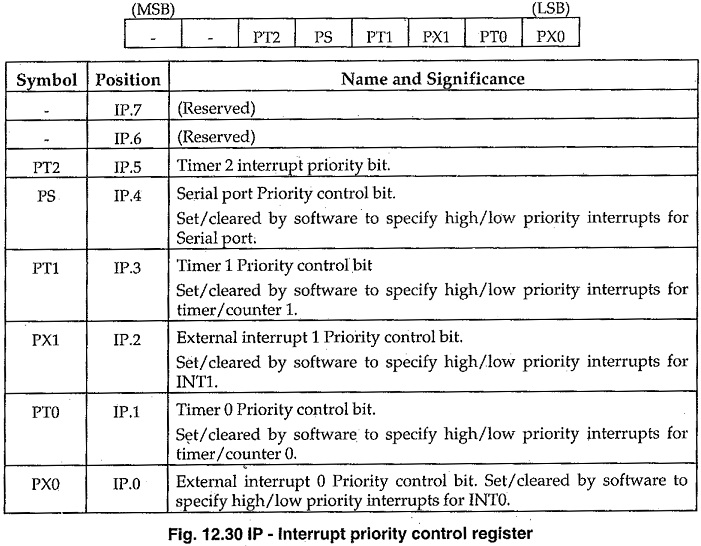
Each interrupt source can also be individually programmed to one of two priority levels by setting or clearing a bit in Special Function Register IP (Fig.12.30). A low-priority interrupt can itself be interrupted by a high-priority interrupt, but not by another low priority interrupt. A high-priority interrupt can’t be interrupted by any other interrupt source.
If two requests of different priority levels are received simultaneously, the request of higher priority level is serviced. If requests of the same priority level are received simultaneously, an internal polling sequence determines which request is serviced. Thus within each priority level there is a second priority structure determined by the polling sequence, as follows :
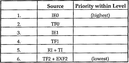
Note that the “priority within level” structure is only used to resolve simultaneous requests of the same priority level.
The IP register contains a number of unimplemented bits. IP.7 and IP.6 are vacant in the 8052s, and in the 8051 Interrupts these and IP.5 are vacant. User software should not write is to these bit positions, since they may be used in future MCS-51 products.
External Interrupts:
The external sources can be programmed to be level-activated or transition-activated by setting or clearing bit IT1 or IT0 in Register TCON. If ITx = 0, external interrupt x is triggered by a detected low at the INTx pin. If ITx = 1, external interrupt x is edge-triggered. In this mode if successive samples of the INTx pin show a high in one cycle and a low in the next cycle, interrupt request flag IEx in TCON is set. Flag bit IEx then requests the interrupt.
Since the external interrupt pins are sampled once each machine cycle, an input high or low should hold for at least 12 oscillator periods to ensure sampling. If the external interrupt is transition-activated, the external source has to hold the request pin high for at least one machine cycle, and then hold it low for at least one machine cycle to ensure that the transition is seen so that interrupt request flag Mx will be set. IEx will be automatically cleared by the CPU when the service routine is called.
If the external interrupt is level-activated, the external source has to hold the request active until the requested interrupt is actually, generated. Then it has to deactivate the request before the interrupt service routine is completed, or else another interrupt will be generated.
Single-Step Operation:
The 8051 Interrupts structure allows single-step execution with very little software overhead. As previously noted, an interrupt request will not be responded to while an interrupt of equal priority level is still in progress, nor will it be responded to after RETI until at least one other instruction has been executed. This, once an interrupt routine has been entered, it cannot be re-entered until at least one instruction of the interrupted program is executed. One way to use this feature for single-step operation is to program one of the external interrupts (say, INT0) to be level-activated. The service routine for the interrupt will terminate with the following code :

Now if INT0 pin, which is also the P3.2 pin, is held normally low, the CPU will go right into the External Interrupt 0 routine and stay there until INT0 is pulsed (from low to high to low). Then it will execute RETI, go back to the task program, execute one instruction, and immediately re-enter the External Interrupt 0 routine to await the next pulsing of P3.2. One step of the task program is executed each time P3.2 is pulsed.