Ungrounded Neutral System:
In an ungrounded neutral system, the neutral is not connected to the ground i.e. the neutral is isolated from the ground. Therefore, this system is also called isolated neutral system or free neutral system. Fig. 26.7 shows ungrounded neutral system. The line conductors have capacitances between one another and to ground. The former are delta-connected while the latter are star-connected. The delta-connected capacitances have little effect on the grounding characteristics of the system (i.e. these capacitances do not effect the earth circuit) and, therefore, can be neglected. The circuit then reduces to the one shown in Fig. 26.8(i).
Circuit behaviour under normal conditions: Let us discuss the behavior of ungrounded neutral system under normal conditions (i.e. under steady state and balanced conditions). The line is assumed to be perfectly transposed so that each conductor has the same capacitance to ground.
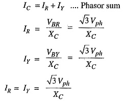
Therefore, CR=CY=CB=C (say). Since the phase voltages VRN,VYN and VBN have the same magnitude (of course, displaced 120° from one another), the capacitive currents IR, Iy and IB will have the same value i.e.
![]()
where
Vph = Phase voltage (i.e. line-to-neutral voltage)
xc = Capacitive reactance of the line to ground.
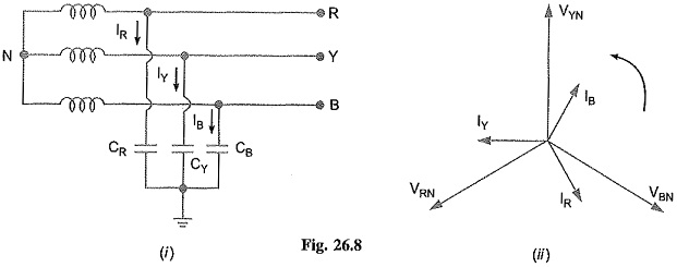
The capacitive currents IR, Iy and IB lead their respective phase voltages VRN,VYN and VBN by 90° as shown in the phasor diagram in Fig. 26.8(11). The three capacitive currents are equal in magnitude and are displaced 120° from each other. Therefore, their phasor sum is zero. As a result, no current flows to ground and the potential of neutral is the same as the ground potential. Therefore, ungrounded neutral system poses no problems under normal conditions. However, as we shall see, currents and voltages are greatly influenced during fault conditions.
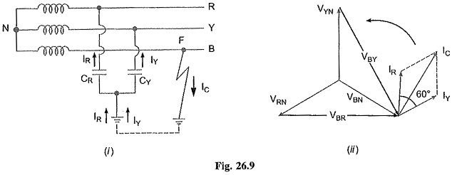
Circuit behaviour under single line to ground-fault: Let us discuss the behaviour of ungrounded neutral system when single line to ground fault occurs. Suppose line to ground fault occurs in line B at some point F. The circuit then becomes as shown in Fig. 26.9(1). The capacitive currents IR and Iy flow through the lines R and Y respectively. The voltages driving IR and Iy are VBR and VBY respectively. Note that VBR and VBY are the line voltages [See Fig. 26.9 (ii)]. The paths of IR and Iy are essentially capacitive. Therefore, IR leads VBR by 90° and Iy leads VBY by 90° as shown in Fig. 26.9 (ii). The capacitive fault current Ic in line B is the phasor sum of IR and Iy.
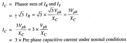
Fault current in line B,
![]() Capacitive fault current n line B is
Capacitive fault current n line B is
Therefore, when single line to ground fault occurs on an ungrounded neutral system, the following effects are produced in the system:
- The potential of the faulty phase becomes equal to ground potential. However, the voltages of the two remaining healthy phases rise from their normal phase voltages to full line value. This may result in insulation breakdown.
- The capacitive current in the two healthy phases increase to √3 times the normal value.
- The capacitive fault current (IC) becomes 3 times the normal per phase capacitive current.
- This system cannot provide adequate protection against earth faults. It is because the capacitive fault current is small in magnitude and cannot operate protective devices.
- The capacitive fault current IC flows into earth. Experience shows that IC in excess of 4A is sufficient to maintain an arc in the ionized path of the fault. If this current is once maintained, it may exist even after the earth fault is cleared. This phenomenon of persistent arc is called arcing ground. Due to arcing ground, the system capacity is charged and discharged in a cyclic order. This sets up high-frequency oscillations on the whole system and the phase voltage of healthy conductors may rise to 5 to 6 times its normal value. The overvoltages in healthy conductors may damage the insulation in the line.
Due to above disadvantages, ungrounded neutral system is not used these days: The modern high-voltage 3-phase systems employ grounded neutral owing to a number of advantages.