Translay System:
This system is the modified form of voltage-balance system. Although the principle of balanced (opposed) voltages is retained, it differs from the above voltage-balance system in that the balance or opposition is between voltages induced in the secondary coils wound on the relay magnets and not between the secondary voltages of the line current transformers. Since the current transformers used with Translay System have only to supply to a relay coil, they can be made of normal design without any air gaps. This permits the scheme to be used for feeders of any voltage.
Constructional details:
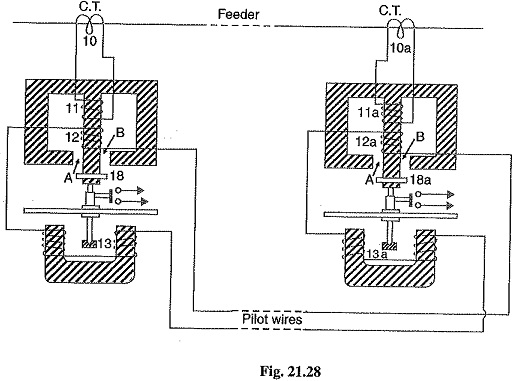
Fig. 21.28 shows the simplified diagram illustrating the principle of Translay System. It consists of two identical double winding induction type relays fitted at either end of the feeder to be protected. The primary circuits (11, 11a) of these relays are supplied through a pair of current transformers. The secondary windings (12, 13 and 12a, 13a) of the two relays are connected in series by pilot wires in such a way that voltages induced in the former opposes the other. The compensating devices (18, 18a) neutralize the effects of pilot-wire capacitance currents and of inherent lack of balance between the two current transformers.
Operation:
Under healthy conditions of Translay System, current at the two ends of the protected feeder is the same and the primary windings (11,11a) of the relays carry the same current. The windings 11 and 11a induce equal emits in the secondary windings 12, 12a and 13, 13a. As these windings are so connected that their induced voltages are in opposition, no current will flow through the pilots or operating coils and hence no torque will be exerted on the disc of either relay. In the event of fault on the protected feeder, current leaving the feeder will differ from the current entering the feeder. Consequently, unequal voltages will be induced in the secondary windings of the relays and current will circulate between the two windings, causing the torque to be exerted on the disc of each relay.
As the direction of secondary current will be opposite in the two relays, therefore, the torque in one relay will tend to close the trip circuit while in the other relay, the torque will hold the movement in the normal unoperated position. It may be noted that resulting operating torque depends upon the position and nature of the fault in the protected zone and at least one element of either relay will operate under any fault condition.
It is worthwhile here to mention the role of closed copper rings (18, 18a) in neutralizing the effects of pilot capacitive currents. Capacitive currents lead the voltage impressed across the pilots by 90° and when they flow in the operating winding 13 and 13a (which are of low inductance), they produce fluxes that also lead the pilot voltage by 90°.
Since pilot voltage is that induced in the secondary windings 12 and 12a, it lags by a substantial angle behind the fluxes in the field magnet air gaps A and B. The closed copper rings (18, 18a) are so adjusted that this angle is approximately 90°. In this way fluxes acting on the disc are in phase and hence no torque is exerted on the relay disc.