Selection of Surge Arresters:
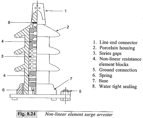
These are non-linear resistors in series with spark gaps which act as fast switches. A Selection of Surge Arresters or lightning arrester is shown in Fig. 8.24 and its characteristics are given in Fig. 8.25. A number of non-linear resistor elements made of silicon carbide are stacked one over the other into two or three sections. They are usually separated by spark gaps (see Fig. 8.24). The entire assembly is housed in a porcelain water-tight housing. The volt-ampere characteristic of a resistance element is of the form![]()
where,
I = discharge current,
V = applied voltage across the element, and
k and a are constants depending on the material and dimensions of the element.
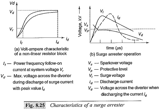
The dynamic characteristics are shown in Fig. 8.25a.
When a surge voltage (Vi of Fig. 8.25b) is applied to the surge arrester, it breaks down giving the discharge current id and maintains a voltage Vd across it. Thus, it provides a protection to the apparatus to be protected above the protective level Vp (see Fig. 8.25b).
The lighter designs operate for smaller duration of currents, while the heavy duty Selection of Surge Arresters with assisted or active gaps are designed for high currents and long duration surges. The lighter design arresters can interrupt 100 to 300 A of power frequency follow-on current and about 5000 A of surge currents. If the current is to be more and has to be exceeded, the number of series elements has to be increased or some other method to limit the current has to be used. In heavy duty arresters, the gaps are so arranged that the are burns in the magnetic field of the coils excited by power frequency follow-on currents. During lightning discharges, a high voltage is induced in the coil by the steep front of the surge, and sparking occurs in an auxiliary gap. For power frequency follow-on currents, the auxiliary gap is extinguished, as sufficient voltage will not be present across the auxiliary gap to maintain an arc. The main gap arcs occur in the magnetic field of the coils. The magnetic field, aided by the horn shaped main gap electrodes, elongates the arc and quanches it rapidly. The follow-on current is limited by the voltage drop across the arc and the resistance element. During surge discharge the lightning protective level becomes low.
Sometimes, it is possible to limit the power frequency and other overvoltages after a certain number of cycles using Selection of Surge Arresters. The permissible voltage and duration depend on the thermal capacity of the arrester. The rated arrester voltage is normally chosen so that it is not less than the power frequency overvoltage expected (line to ground) at the point of installation, under any faulty or abnormal operating condition.
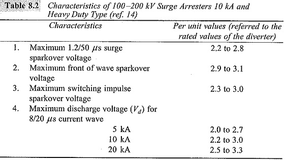
Typical characteristics of Selection of Surge Arresters in the voltage range 100 to 200 kV, 10 kA (heavy duty type) are given in Table 8.2
Surge Arresters for E.H.V. Systems:
The Selection of Surge Arresters voltage rating for EHV and UHV systems depends on
- the rate of rise of voltage,
- the type of system to be handled, i.e. whether effectively grounded or grounded through an impedance etc., and
- operating characteristic of the arrester.
The usual type of surge arresters used for the above purposes are
- silicon carbide arresters with spark gaps,
- silicon carbide arresters with current limiting gaps, and
- the gapless metal oxide (zinc oxide) arresters.
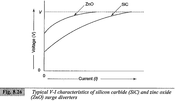
The first two types of arresters have a V-I characteristic of the nature of V = AIn, where n varies between 0.5 and 0.6 for the elements. The time to sparkover for the first type of arresters is around 1 to 2 μs and the voltage is limited to 2.0 p.u. of the power frequency voltage. The V-I characteristics of arresters with no spark gaps are not enough to limit the power frequency follow-on current, while the arresters with the spark gap provided will have a high limiting voltage. Further, arresters with spark gaps are not very well suited to limit the switching overvoltages. However, recent developments in solid state technology have led to the development of metal oxide non-linear resistors. With the use of these materials, the new class of Selection of Surge Arresters that can handle very small to very large current, with almost constant voltage across them, have been developed. One such arrester is the zinc oxide (ZnO) arrester which uses a base material of ZnO) sintered into a different insulating medium such as BiO3. The V-I characteristic of such a unit is of the form V α In where n = 0.02 to 0.03. The V-I characteristics of silicon carbide and zinc oxide arresters are shown in Fig. 8.26 for comparison.
The advantages of zinc oxide arresters for EHV systems are
- they are simple in construction,
- they have flat V-I characteristic over a wide current range, and
- the absence of a spark gap that produces steep voltage gradients when sparking occurs.
The main disadvantage of zinc oxide arresters is the continuous flow of power frequency current and the consequent power loss. Voltage grading system is not needed for each of the units of the zinc oxide arresters used in EHV systems. A typical 400 kV line arrester may be rated at 15 kA and may have a resistance of 100 ohms at the peak current rating.
Protection of Lines with Surge Arresters:
Since surge arresters are devices that provide low resistance paths for overvoltages through an alternate ground path, their operating characteristics and application is of importance. The spark gap inside the arrester acts as a fast acting switch while non-linear arrester elements provide the low impedance ground path. The arrester voltage at its terminal when connected to a line of surge impedance Z to ground, is given as
![]()
where,
Z is the line surge impedance,
R is the resistance of the non-linear element,
r is the ground to earth resistance, and
u(t) is the surge voltage.
The Thevinin equivalent circuit for the arrester is shown in Fig. 8.27.
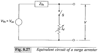
The switch S is open for voltages less than the sparkover voltage of the surge arrester Vs, while it is closed for voltage magnitudes greater than Vs. The closing of the switch is represented by injecting a voltage cancellation wave having a negative amplitude equal to the potential difference between the voltage that appears when the switch is open Voc, and the voltage developed across the impedance of the device after the switch is closed. ZTh is the impedance of the system viewed from the terminals of the protective device.