Magnetic Circuit Problems:
2.1 A square loop of side 2d is placed with two of its sides parallel to an infinitely long conductor carrying current I. The centre line of the square is at distance b from the conductor. Determine the expression for the total flux passing through the loop. What would be the loop flux if the loop is placed such that the conductor is normal to the plane of the loop. Does the loop flux in this case depend upon the relative location of the loop with respect to the conductor?
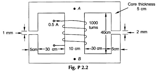
2.2 For the magnetic circuit of Fig. P.2.2, find the flux density and flux in each of the outer limbs and the central limbs. Assume the relative permeability of iron of the core to be (a) ∞, (b) 4500.
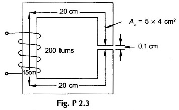
2.3 For the Magnetic Circuit Problems shown in Fig. P2.3, calculate the exciting current required to establish a flux of 2 mWb in the air-gap. Take fringing into account empirically. Use the B-H curve of Fig. 2.15.
2.4 A steel ring has a mean diameter of 20 cm, a cross-section of 25 cm2 and a radial air-gap of 0.8 mm cut across it. When excited by a current of I A through a coil of 1000 turns wound on the ring core, it produces an air-gap flux of 1 mWb. Neglecting leakage and fringing, calculate (a) relative permeability of steel, and (b) total reluctance of the magnetic circuit.
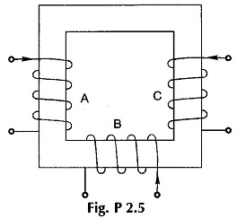
2.5 The core made of cold rolled silicon steel (B-H curve of Fig. 2.15) is shown in Fig. P2.5. It has a uniform cross-section (net iron) of 5.9 cm2 and a mean length of 30 cm. Coils A, B and C carry 0.4, 0.8 and 1 A respectively in the directions shown. Coils A and B have 250 and 500 turns respectively. How many turns must coil C have to establish a flux of 1 mWb in the core?
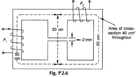
2.6 In the Magnetic Circuit Problems shown in Fig. P2.6, the coil F1 is supplying 4000 AT in the direction indicated. Find the AT of coil F2 and current direction to produce air-gap flux of 4 mWb from top to bottom. The relative permeability of iron may be taken as 2500.
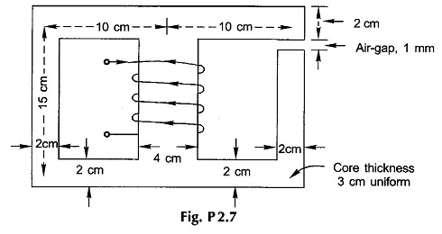
2.7 For the magnetic circuit shown in Fig. P.2.7, the air-gap flux is 0.24 mWb and the number of turns of the coil wound on the central limb is 1000.Calculate (a) the flux in the central limb, (b) the current required. The magnetization curve of the core is as follows:
![]()
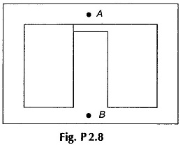
2.8 The Magnetic Circuit Problems shown in Fig. P2.8 has a coil of 500 turns wound on the central limb which has an air-gap of 1 mm The magnetic path from A to B via each outer limb is 100 cm and via the central limb 25 cm (air-gap length excluded). The cross-sectional area of the central limb is 5 cm x 3 cm and that each outer limb is 2.5 cm x 3 cm. A current of 0.5A in the coil produces an air-gap flux of 0.35 mWb. Find the relative permeability of the medium.
2.9 A cast steel ring has an external diameter of 32 cm and a square cross-section of 4 cm side. Inside and across the ring a cast steel bar 24 x 4 x 2 cm is fitted, the butt-joints being equivalent to a total air-gap of 1 mm. Calculate the ampere-turns required on half of the ring to produce a flux density of 1 T in the other half. Given:
![]()
2.10 In Prob. 2.2 the B-H curve of the core material is characterized by the data given below. Find now the flux and flux densities in the three limbs of the core.
![]()
2.11 A ring of magnetic material has a rectangular cross-section. The inner diameter of the ring is 20 cm and the outer diameter is 25 cm, its thickness being 2 cm. An air-gap of 1 mm length is cut across the ring. The ring is wound with 500 turns and when carrying a current of 3 A produces a flux density of 1.2 T in the air-gap. Find (a) magnetic field intensity in the magnetic material and in the air-gap, (b) relative permeability of the magnetic material, and (c) total reluctance of the magnetic circuit and component values.
2.12 For the magnetic ring of Prob. 2.11, the exciting current is again 3 A. Find the following:
- Inductance of the coil,
- energy stored in the magnetic material and in the air-gap, and
- rms emf induced in the coil when it carries alternating current of 3 sin 314t.
2.13 Assume that the core of the magnetic circuit of Fig. P2.3 has μr = 2500.
- Calculate the energy stored in the core and in the air-gap for an excitation current of 5 A. What will be these values if µr = ∞?
- What will be the excitation current to produce a sinusoidally varying flux of 0.5 sin 314t mWb in the air-gap?
- Calculate the inductance of the coil. What will be the inductance if µr = ∞?
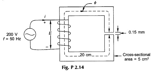
2.14 The Magnetic Circuit Problems of Fig. P2.14 has a magnetic core of relative permeability 1600 and is wound with a coil of 1500 turns excited with sinusoidal ac voltage, as shown. Calculate the maximum flux density of the core and the peak value of the exciting current. What is the peak value of the energy stored in the magnetic system and what percentage of it resides in the air -gap?
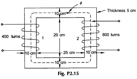
2.15 The material of the core of Fig. P2.15, wound with two coils as shown, is sheet steel (B-H curve of Fig. 2.15). Coil 2 carries a current 2 A in the direction shown. What current (with direction) should coil 1 carry to establish a flux density of 1.4 T in the core in the indicated direction?
2.16 The flux in a magnetic core is alternating sinusoidally at a frequency of 600 Hz. The maximum flux-density is 2 T and the eddy-current loss is 15 W. Find the eddy-current loss in the core if the frequency is raised to 800 Hz and the maxi-mum flux density is reduced to 1.5 T.
2.17 The core-loss (hysteresis + eddy-current loss) for a given specimen of magnetic material is found to be 2000 W at 50 Hz. Keeping the flux density constant, the frequency of the supply is raised to 75 Hz resulting in core-loss of 3200W. Compute separately hysteresis and eddy-current losses at both the frequencies. Since Bm remains constant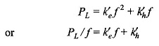
which gives a straight line from which k′e and k′h can be determined.
2.18 A permanent magnet (PM) made of neodymium-iron boron alloy is placed in the magnetic circuit of Fig. P 2.18. Given
![]()
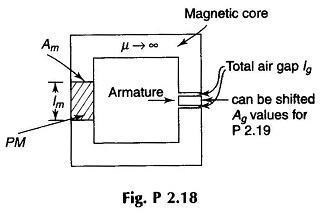
It is desired to have air gap flux density Bg = 0.5 T. For optimum design (minimum volume of PM) determine lm.
2.19 In the PM circuit of Fig. P 2.18, Ag is reduced to 2 cm2. Determine Bg and Bm.
2.20 The armature in the PM circuit is now taken out and its height reduced so that when it is placed back in the circuit the air gap length lg is now 0.5 cm. Determine Bg and Bm.
2.21 On the core of Fig. 2.18 an exciting coil is wound with 200 turns and is fed with an exciting current of 1 A. Determine air-gap flux density Bg. Note that direction of exciting current is such that it aids magnetization.