Attenuators:
Attenuators are designed to change the magnitude of the input signal seen at the input stage, while presenting a constant impedance on all ranges at the attenuator input.
A compensated RC attenuator is required to attenuate all frequencies equally. Without this compensation, HF signal measurements would always have to take the input circuit RC time constant into account.
The input attenuator must provide the correct 1-2-5 sequence while maintaining a constant input impedance, as well as maintain both the input impedance and attenuation over the frequency range for which the oscilloscope is designed.
Uncompensated Attenuators:
The circuit diagram shown in Fig. 7.47 gives a resistive divider attenuator connected to an amplifier with a 10 pf input capacitance. If the input impedance of the amplifier is high, the input impedance of the attenuator is relatively constant, immaterial of the switch setting of the attenuator.
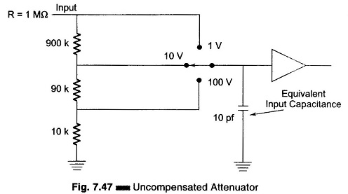
The input impedance, as seen by the amplifier, changes greatly depending on the setting of the attenuator. Because of this, the RC time constant and frequency response of the amplifier are dependent on the setting of th- attenuator, which is an undesirable feature.
Simple Compensated Attenuator:
The diagram in Fig. 7.48 shows an attenuator with both resistive and capacitive voltage dividers. The capacitive voltage dividers improve the HF response of the attenuator. This combination of capacitive and resistive voltage dividers is known as a compensated attenuator. For oscilloscopes where the frequency range extends to 100 MHz and beyond, more complex dividers are used.
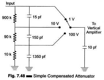
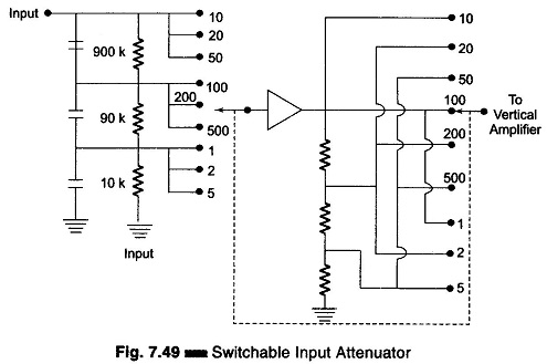
Figure 7.49 shows an attenuator divider between the input and output of the vertical deflection pre-amplifier. The input attenuator provides switching powers of 10, while attenuators at the output of the vertical preamplifier provides 1-2-5 attenuation.
Practically all oscilloscopes provide a switchable input coupling capacitor, as shown in Fig. 7.49.
The input impedance of an oscilloscope is 1 MΩ which is shunted with an input capacitance of 10-30 pf. If a probe were connected to the oscilloscope, the input impedance at the probe tip would have a greater capacitance because of the added capacitance of the probe assembly and of the connecting shielded cable. If it is desired for HF oscilloscopes to have an input capacitance of much less than 20-30 pf, an attenuator probe is used. Figure 7.48 shows a 10 to 1 attenuator probe connected to the input of the oscilloscope.
Within the probe tip is a 9 MΩ resistor and shunted across this resistor is a capacitor. This capacitor is adjusted so that the ratio of the shunt capacitance to the series capacitance is exactly 10 to 1.
The attenuator probe, often called a 10 to 1 probe, provides an approximately 10 to 1 reduction in the input capacitance. However, it also gives a 10 to 1 reduction in overall oscilloscope sensitivity.
The input capacitance is not constant from one oscilloscope to another hence the probe is provided with an adjustable compensating capacitor. If the ratio of the series to shunt is not adjusted precisely to 10 to 1, the frequency response of the oscilloscope will be flat.