Transient Response of Closed Loop Drive System:
The Transient Response of Closed Loop Drive System is of fundamental importance and must be investigated in detail. The time response of a system to specified inputs gives information with respect to the following characteristics:
1.Whether the system is stable or unstable. The system is said to be stable if it reaches a steady-state condition which has the same form as the input disturbance. It is said to be unstable if it does not attain an appropriate steady state condition.
2.The possible oscillatory nature of the system and the peak amplitudes of the oscillations.
3.The damping of the system oscillations which is a measure of the speed or sluggishness of the system. An underdamped system even though it gives an oscillatory output has a fast response. On the otherhand an overdamped system is sluggish and does not have oscillatory behaviour.
4.Steady-state error of the system which is actually a measure of the ‘goodness’, indicating how exactly the output can follow the input. Transient Response of Closed Loop Drive System have very small steady-state error and thus have an output following the input very closely, compared to open loop systems.
The parameters of the system actually influence the above characteristics. It is possible to adjust the parameters to give the desired performance with respect to the above characteristics. If the, system has parameters already adjusted to the extent possible and the system is not giving the desired performance, additional controllers are added to the given system to improve the performance.
The time response of the system has two parts; the transient and steady-state response. The transient response is the time variation of the output variable while going from one state to the other. The steady-state response of the system is the time variation of the output variable as the time approaches infinity.
A stable linear time invariant system comes back to its original state of equilibrium when the system is subjected to a disturbance, whereas an unstable system has its output variable in a continuous state of oscillation or it diverges very much without bounds from the state of equilibrium. The characteristic nature of stability (either absolute or relative) of the system can be very easily assessed without need for determining the time response. Stability tests are available and can be applied to decide whether the system is stable or not.
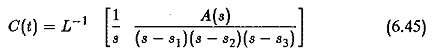
The time domain response can be obtained by directly solving the equations of the system. It is normally determined for step input, because it enables us to determine the time response of the system for any other type of input. Thus, the step response of a system is very important. However, the direct solution of the equation is rather tedious when the order is more. The method of Laplace transform can be applied to solve the equations. It has been very well utilised to obtain the transfer function, which is the ratio of the Laplace transform of output variable to the Laplace transform of input variable. The inverse transform of the output variable after substituting the Laplace transform of input variable gives the time response of the system. The procedure is illustrated with respect to a typical transfer function.
Let the transfer function be
The denominator polynomial is solved and its roots are found out. These are the poles of the transfer function. Therefore
![]()
The system has step input. Therefore
![]()
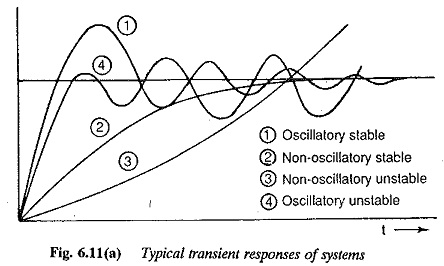
which is the sum of the residues of the function at poles s1,s2,s3.. Assuming that these do not repeat, which is normally the case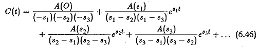
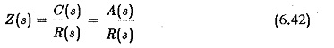
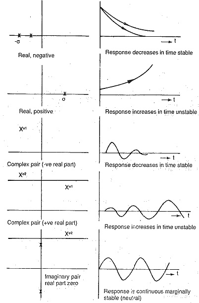
If the poles are real, the time response C(t) is made up of constants and a sum of exponential functions. The output is an aperiodic function having no oscillations. When the poles are complex, they appear in complex conjugate pairs. The time response in this case shows harmonic oscillations. The time response may result in a decreasing, neutral, or increasing response depending upon the nature of the roots. The transient response of C(t) decreases and oscillations if any are damped out, if the poles of the transfer functions have negative real parts. It has sinusoidal oscillations of constant magnitude if the real parts are zero. The transient response of the system, on the other hand, is unbounded in its magnitude if one or more roots have positive real parts. This nature of the transient response clearly defines the stability of the system. In the first case the system is stable, in the second case it is neutral and in the third case it is unstable. These are depicted in Fig. 6.11. We can also see that in the first case the roots lie on the left hand side of the s-plane, in the second case they lie on the imaginary axis and in the third the roots with positive real parts lie on the right hand side of the s-plane. Therefore the stability of the system may be related to the location of poles on the s-plane. For absolute stability of a control system it is a necessary and sufficient condition that all the poles of the transfer function have negative real roots and lie on the left hand side of the s-plane.
When once the system is found to be stable having a bounded output, the quality of the time response is judged by certain time domain specifications, such as overshoot, rise time, peak time, swiftness of response, settling time, etc. The system must have fast response so that it settles down to its new equilibrium position quickly. As a fast response is always accompanied by oscillations this cannot be achieved in systems where oscillations cannot be tolerated. The system must also have a smaller overshoot. To achieve this it must have sufficient damping. Two typical time responses are depicted in Fig. 6.12. From the figure it is dear that a fast response is possible with smaller damping resulting in smaller rise time and larger overshoot. An increase in damping results in an increase in rise time and decrease in overshoot. Therefore any attempt to make the system faster it is followed by increased overshoot. The system becomes sluggish if an attempt is made to decrease the overshoot. It is therefore difficult to have a system with smaller rise time as well as overshoot. A compromise must be made between these two specifications.
It is possible to determine the time domain response for any system and adjust its parameters to correct this easily for second order systems. As the order of the system increases the procedure becomes tedious. In such cases a higher order system is approximated to a second order system having the effects of dominant pole pair.
Let us consider a third order system of normalised natural frequency, in which case it has a Transient Response of Closed Loop Drive System is given by
![]()
The effect of the pole s = -1/β on the transient response is shown in Fig. 6.13. The effect of this pole is insignificant if |1/β|≥10|ωnε| and the system has a response similar to that of a second order system. The location of the pole is significant, i.e., as it moves nearer to the imaginary axis the time response is altered.
Further, the presence of a zero in the transfer function also alters the transient performance. Its relative position with respect to the additional pole is also important. If this zero is to the left of the pole the system behaves as if it has only complex poles but with smaller peak overshoot. If the zero is to the right of the pole the overshoot is greater than that of the system with complex poles.
Therefore the approximation of a higher order system must be made with caution. However they may be approximated to a system having
(a) two complex poles
(b) two complex poles and one real pole and
(c) two complex poles, one real pole and one real zero.
In the first case it is a second order system for which the time domain specifications can be determined. In the second case depending upon the location of the third pole the performance can be corrected to achieve the desired performance. In the third case their effect will be small if they are very near to each other.
The response of a second order system is therefore very important. A detailed inspection of this response with reference to time domain specification is given in the following.
Using generalised notation the Transient Response of Closed Loop Drive System of a second order system is given by
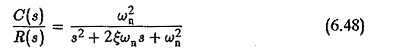
where
ωn is natural frequency of the system
ε is damping ratio.
Time domain response is normally defined for step input in which case
![]()
The time response
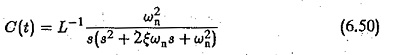
which can be obtained as
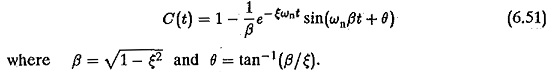
The transient response of a second order system is shown in Fig. 6.12. As the value e decreases the closed loop roots approach the imaginary axis and the response is oscillatory and the % overshoot also increases.
From these two equations it is clear that the smaller the value of ε the larger the overshoot and smaller the peak time. The system is faster. A compromise has to be made between the swiftness of the response and allowable overshoot.