Six Pulse Converter with Interphase Transformer:
The basic connection of a Six Pulse Converter with Interphase Transformer is shown in Fig. 3.38. This is obtained by connecting two three pulse converters in parallel on the dc side. The interphase transformer absorbs the difference of the instantaneous voltages of the two converters. The total load current is shared by the two converters and hence is the sum of the individual converter currents.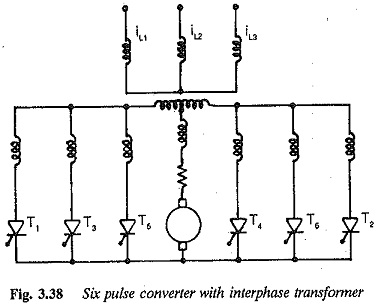
![]()
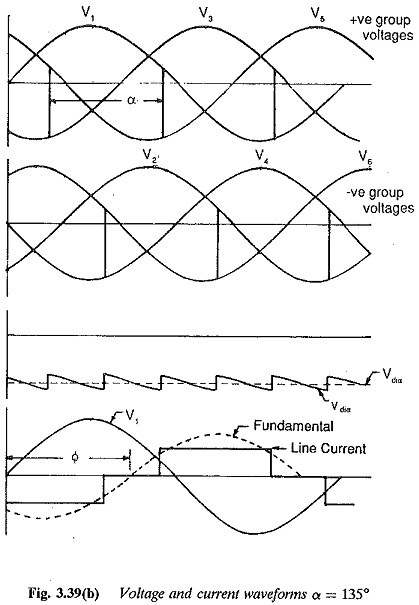
The output voltages of individual converters have a ripple content of frequency 3f. Owing to the phase difference between the instantaneous values of output voltages, the net dc voltage has a reduced ripple content and a pulse frequency of 6f. This means the output voltage is made up of six segments of dc voltage. A thyristor conducts for 120° and there is, therefore, a good utilisation of the thyristor and transformers. The current and voltage waveforms for α = 45° and α = 135° are depicted in Figs 3.39(a) and (b), From these figures it is clear that the average dc voltage of the converters is the same, but the instantaneous values are different. The latter differ because of the phase difference between the output voltages of the converters. The parallel connection of the two converters must be made through an interphase transformer, so that difference between the instantaneous voltages becornes a voltage drop across the reactor.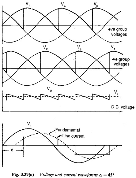
If VdI and VdII are the voltages of the individual converters and Vtr the voltage across the interphase transformer, we have (referring to Figs 3.38 and 3.39).
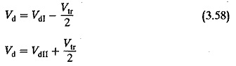 From these equations we have
![]()
This shows that the pulse number is six and the amplitude of the ripple is smaller than that of individual converters.
From the equation we have,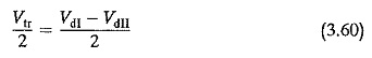
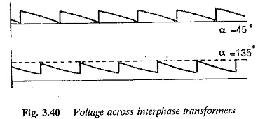
which is the voltage across one half of the interphase transformer. The voltage across the interphase transformer and the mean dc voltage are shown in Fig. 3.40 for α = 90°. The voltage across the interphase transformer is non–sinusoidal. This results in a non-sinusoidal magnetising current of the transformer. It has a frequency of 3f. The dc load current is superimposed by this magnetising current. On the other hand, for α = 0 the magnetising current is sinusoidal. Because of the centre tap, the dc current flows simultaneously in each half of the transformer which avoids premagnetisation of the core. The peak value of the ac current must be very small compared to the load current, which should not fall below a critical value. This critical value is the peak value of the magnetising current. In case the load current is less than the critical value, the converter operates as a normal six pulse midpoint converter. Considering this fact, the mean value of the dc voltage of the converter is
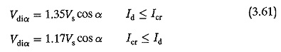
The thyristors conduct for 60° in the former case and for 120° in the latter.Therefore, as the load current increases there is first a significant voltage drop of 15% due to transition, or a sudden rise if the load current is below Icr. The mean value of the dc voltage of the converter under ideal conditions with an interphase transformer is
![]()
The converter operates as a rectifier in the range of firing angles 0 < α < 90° and as an inverter for 90° < α < 180°. Each converter group is an individual commutator group with three commutations independent of each other. There are six commutations, which are not simultaneous.
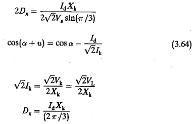
As has already been discussed, the terminal voltage falls when the thyristor conduction is increased to 120° using an interphase transformer. The terminal voltage of the converter is affected by the overlap in the same manner as in the other types of converters discussed previously. If the drop due to overlap be Dx we have![]()
Other factors that influence the terminal voltage are the forward voltage drop of the device and the resistance drop. Therefore![]()
The secondaries, carrying current in the same direction, are wound on the same core limb to avoid saturation.
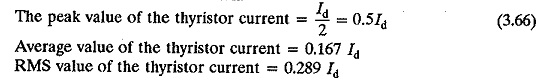
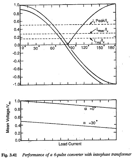
The peak forward or inverse voltage of the thyristor is 2.095 Vdio or √2VL. The reverse voltage occurs during inversion. The thyristors do not have a sudden rise of voltage in the forward direction. Six channels of firing phases, separated by 60° each, with a single firing pulse in each channel are required. The power factor, displacement factor, etc., describing the performance of the converter, are depicted in Fig. 3.41 in graphical form.
The secondaries share the load current. Two three pulse systems, each with half dc current have the secondary rating as a three-pulse connection. The rating of the secondary
![]()
The RMS value of the primary winding current is Id ∕ √6.
The primary rating is PP = 1.05Pdi.
The design rating of the transformer is
![]()
The interphase transformer acts as a common smoothing inductance. The extra load inductance required may be small and there is little tendency to conduct discontinuously. The interphase connection is used in applications where large dc currents are required at low voltage outputs.