Decade Counter Circuit:
A Decade Counter Circuit is of flip-flops (F/Fs) in cascade, which counts in the base 10 (decimal number system). This means that there is a sequence of ten distinct counts in increasing order. Three F/Fs used in cascade progress through 8 distinct counts (binary numbers from 000 to 111), while 4 F/Fs in cascade progress through 16 distinct states (binary numbers 0000 to 1111).
Hence to get a count of 10, a minimum of 4 F/Fs are required (because 8 distinct states are less while 16 are too many for a decade counter). This problem can be overcome by using 4 F/Fs in Cascade and resetting the output of each F/F to 0 after the desired 10 counts. Figure 6.13 (a) shows a working of decade counter Circuit using 4 negative edged triggered F/Fs in cascade.
The outputs of the F/F B and D are high (equal to binary 1) after 10 pulses have been applied to the counter. Therefore, the output signal of the decade counter is 1010. This output has to be reset on the very next pulse which is done by the use of an AND gate that resets all F/F’s to 0, when the outputs of B and D are 1.
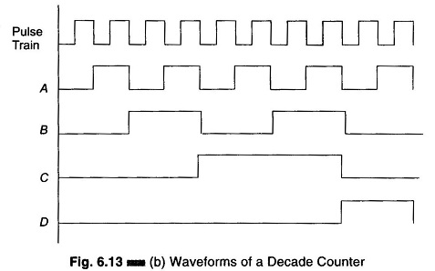
The waveform shown in Fig. 6.13 (b) shows the pulse train applied to the trigger input (clock) of the decade counter (shown in Fig. 6.13(a)) and the output waveform of each F/F.
At the beginning all the F/Fs are reset to 0000. The clock pulse is applied to the trigger input T of the F/F. Since this is a negative edged triggered F/F, at the negative edge or falling edge of the trigger input the F/F A will toggle and hence the output of F/F A changes to level 1; all other F/Fs undergoes no change. The outputs from the F/Fs will be 0001.
At the next clock pulse the F/F A will toggle back to 0, and the output of F/F A falls from 1 to 0 and is applied to the T input of the next F/F B, toggling it. The output of the F/F B changes to 1 and the output of the Decade Counter Circuit goes to 0010.