Brushless DC Motor:
The term Brushless DC Motor is applied to many configurations of ac synchronous motors in which semiconductor control is used to control stator currents such that maximum torque is obtained at a given speed. In a conventional motor the mechanical contactor, the commutator, maintains 90° elect degrees space displacement between the rotor and stator magnetic fields to provide for the required torque.
Theoretically, the stator and rotor functions of a machine can be inverted, putting the field system on the rotor. There is no advantage to be gained if conventional commutation is used, as the commutator sections are fixed and the brush gear must rotate at the speed of the rotor field. Solid-state switching by transistors or thyristors, triggered by position sensors can, however, replace the brush gear by fully electronic commutation, endowing small machines with a valuable control facility. In this method, each phase of stator winding is energized sequentially by a power transistor (or thyristor) by means of a signal from position sensor placed on the rotor. Because of rotor position feedback triggering of thyristors/transistors, the stator and rotor field always remain in synchronism as the frequency of triggering automatically adjusts to motor speed. The length of on-time of the transistors determines motor torque magnitude. Thus by means of electronic circuitry brushless motors can be controlled for both constant and variable torque operation.
The Brushless DC Motors while being generally more expensive for the same kW rating, than commutator and brush motors possess certain advantages over conventional motors.
Advantages of Brushless DC Motor:
- They require little or no maintenance.
- They have a much longer operating life.
- There is no risk of explosion or possibility of RF radiation due to arcing.
- They produce no brush or commutator particles or gases as byproducts of operation.
- They are capable of operation submersed in fluids, combustible gases and may even be hermetically sealed.
- They are generally more efficient than brush-type dc servomotors or conventional dc motors.
- They provide a more rapid response and a fairly linear output torque vs input current characteristic, which lends itself to servo applications.
Brushless DC Motor Schematic and Operation Principle:
The schematic diagram of a Brushless DC Motor is shown in Fig. 8.82. It also shows the three phases of the stator (armature) and rotor with d- and q-axes indicated therein. The stator is connected to a variable voltage current source through an inductor and an inverter comprising six SCRs (S1 to S6). In place of SCRs, power transistor or FETs could be used according to power rating of the motor. Diodes are connected across SCRs to protect these from the L(di/dt) voltage induced in the armature coil undergoing commutation. Position sensors placed on the rotor provide signal to the sensor decoders and gate drivers which cause the SCRs to be fired in sequence so as to be in synchronism with the rotor’s mechanical position. The stator and rotor fields thus get locked into each other and remain in synchronism at any rotor speed.
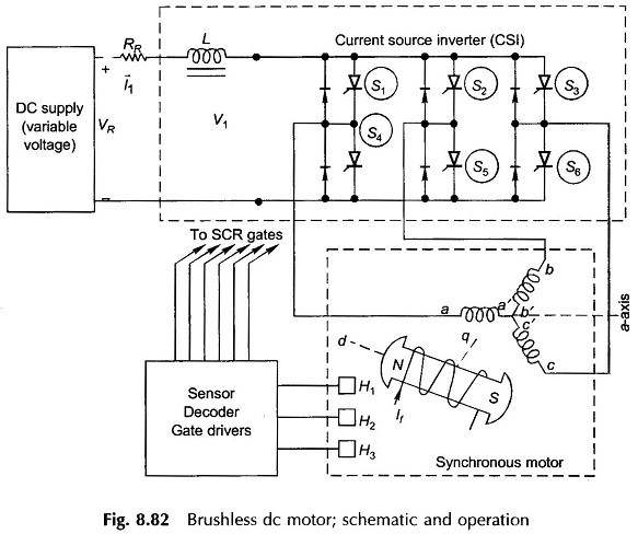
Ideal phase currents are pulses of ± I lasting 120° elect each half and displaced from each other 120° elect phase to phase as shown in Fig. 8.83. Actual current wave forms differ from the ideal rectangular current waves by gradual rises and falls. Such an inverter where ac current flows in form of constant current pulses is known as Current Servo Inverter (CSI).
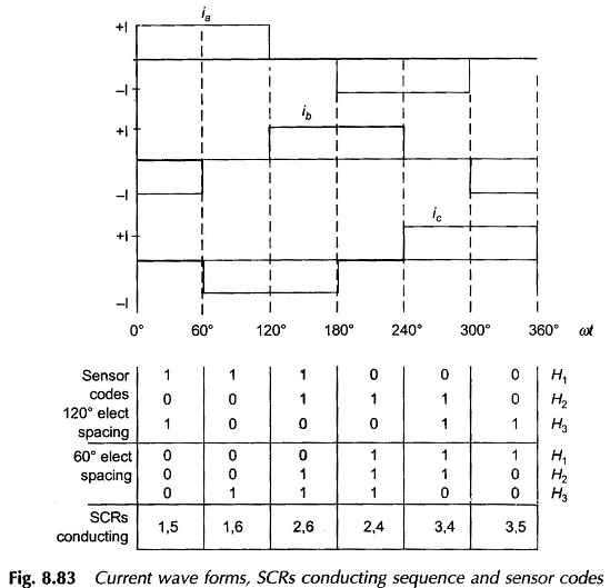
Sequence of inverter firing as shown in Fig. 8.83 immediately follows from the phase current wave forms. For this sequence of SCR firing 120° or 60° elect spaced sensor codes are generated by means of light sensitive or Hall effect sensors. Figure 8.84 illustrates the case of 120° spacing wherein these light sensitive sensors are shown fixed 120° apart receiving light from a fixed light source. The rotor carries a commutating disc with 180° cut-out so that as it rotates with the rotor the light sensors receive light for 180° and are dark for 180°. Sensors produce logic ‘1’ while receiving light and logic ‘0’ when dark. It is easily seen that the three sensors (fixed) and commutating disc (rotating with rotor) produce sensor code sequence as given in Fig. 8.83 from which electronic circuitry generates gating pulses for firing SCRs in the sequence as indicated in the figure.
The relative position of the commutating disc can be adjusted w.r.t. the rotor poles (i.e. w.r.t. d- and q-axis). For the instantaneous rotor position (with discs fixed as indicated) it is seen that the sensor code is just going to change from 101 to 100. The phase ‘a’ is in the middle of its current pulse when the current is commuting from phase b to c. At this instant the resultant stator field F̅1 is oriented along the a-axis as shown in Fig. 8.83 (motoring current’s positive direction is opposite to the positive direction of induced emf); check in phase ‘a’ by applying Fleming’s right hand rule. North pole on stator is thus oriented along the a-axis.
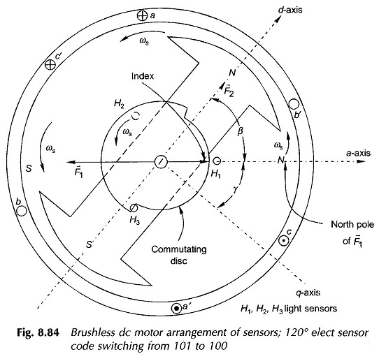
This north pole pushes the rotor north to create motoring torque (angle between rotor and stator N-poles is β).An index marker can be made on the commutating disc which always points to stator north as the stator field rotates in synchronism with the rotor. This index makes an angle γ with the q-axis of the rotor (lagging d-axis by 90°). Obviously (β + γ) = 90∘. The angle may be adjusted by moving the commutating disc on the shaft related to the rotor poles.
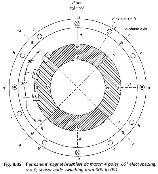
A permanent magnet Brushless DC Motor using Hall effect sensors with 60° elect spacing is shown in Fig. 8.85. Sensors generate logic 1′ when exposed to N-pole and ‘0’ otherwise. The sensor code sequence for this arrangement is easily visualized and is given in Fig. 8.83. With H3 located along a-axis, the sensor code at the rotor position shown is switching from 000 to 001, which means the current is in the middle of conduction for phase ‘a’ and it is changing over from b to c. Thus F1 is directed along a-axis or stator N-pole is along g-axis i.e. γ = 0 (see Fig. 8.84). Permanent magnet motors are usually adjusted for this value of γ (this corresponds to β = 90°, best for torque production).
Brushless DC motor Circuit Diagram:
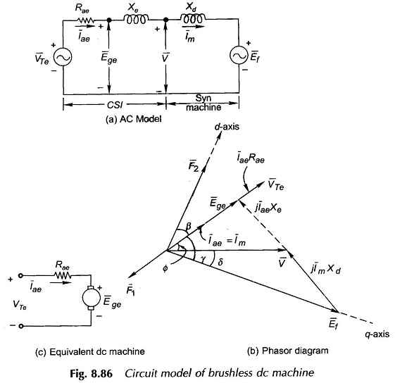
Novotny-Abbas circuit model of a CSI fed Brushless DC Motors is drawn in Fig. 8.86. Currents (balanced) flowing in the synchronous machine of the brushless dc machine set up of Fig. 8.82 are rectangular pulses ac as shown in the wave forms of Fig. 8.83. Actual currents are somewhat rounded pulses. Our analysis will be based on the fundamental ac current and harmonic currents will be ignored. These produce space harmonic air-gap fields which being nonstationary w.r.t. the rotor field produce net zero torque.
Let
I1 = Current fed to the inverter by dc source
Then
Im (rms phase current = fundamental current
= (√6 / π) I1 ; can be shown by Fourier series
In Fig. 8.86(a) the synchronous machine model is the usual one characterized by direct-axis synchronous reactance Xd and excitation emf Ef where Xd and Ef both vary directly with speed which governs the frequency of operation. Ef magnitude is of course related to the rotor field current by the magnetization characteristic. The corresponding phasor diagram is drawn in Fig. 8.86(b) where Im, the phase current, is drawn leading V (ac output voltage/terminal voltage of synchronous machine) by angle Φ. Leading current operation is performed as it helps in extinction of current in SCR commutation.
We shall now create the ac model of CSI with the conditions:
- Iae = Im
- Circuit parameter of model is resistance Rae.
- Ege and Iae are in Phase.
These conditions will assure that this part of the model indeed represents the equivalent dc machine.
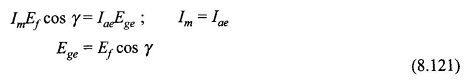
It is also seen from Fig. 8.84 that the phase angle between I̅m = I̅ae and Ef is indeed angle γ. Now equating the converted power per phase of synchronous machine to that of equivalent dc machine we have
Translating this result to the phasor diagram (Fig. 8.86(b)), it becomes clear that V and Ege are related by a fictitious reactance Xe as shown in the circuit of Fig. 8.86(a). We shall now obtain the relationship for VTe and Rae. Neglecting inverter losses
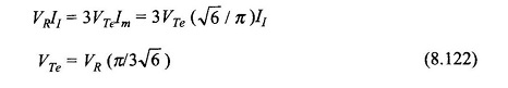
Imagining a short circuit at Ege i.e. Ege = 0, we have
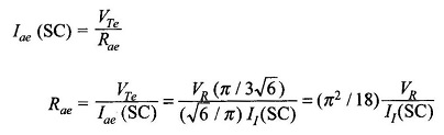
But
VR/ I1(SC) = RR; internal resistance of the rectifier feeding the inverter
Then
![]()
Characteristics of Brushless DC Motor:
With reference to Fig. 8.84(c)
![]()
As already shown in Eq. (8.121)
![]()
But Ef can be written as
![]()
where
- Φf = flux/pole caused by If acting alone.
Substituting values in Eq. (8.124)
![]()
or
Except for the effect of cos γ, this equation is the same as in conventional dc machine.
The torque developed is given by
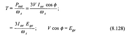
Using Eq. (8.126), we get
![]()
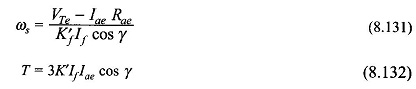
If the magnetization characteristic is assumed linear
![]()
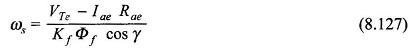
The speed and torque equations then are
In a synchronous motor as the field current is reduced its pf becomes more lagging. But in a Brushless DC Motor (which is a synchronous motor with rotor position feedback) the decrease of field current If causes increase in speed as per Eq. (8.131) like in a conventional dc motor. This can be qualitatively explained by the reasoning that follows. With reference to Fig. 8.86 as If is decreased, Ef and so Ege reduce and as Rae is very small, this causes a disproportionate increase in Iae = Im. The result is rotor acceleration. Increased rotor speed counters Ef reduction and Im increases as the voltage drop ImXd increases with increase in frequency of operation. The result is a steady operation at a new and higher speed at a less leading or even lagging pf.
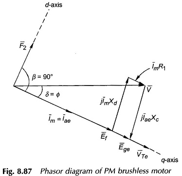
PM Brushless DC Motor:
Small size PM Brushless DC Motor are usually PM kinds. In such a motor rotor mmf F2 remains fixed and also the angle γ in these machines is set to zero which mean that F2 and F1 (armature mmf) are displaced by an angle of 90° (best for torque developed). Further, the phase winding resistance R1 is not negligible so must be added to Rae in the dc model. The phasor diagram for γ = 0 is drawn in Fig. 8.87 wherein the following observations are made
- Xc = capacitive reactance = Xd ( in magnitude).
- PF angle is lagging.
The relationship of Eqs. (8.127) and (8.129) for speed and torque apply except that Eq. (8.124) now modifies as
![]()