Battery Powered Vehicles:
Battery Powered Vehicles – These are popularly known as electric vehicles. Although several batteries and fuel cells have been developed, only available at affordable price is the lead acid battery. Therefore, electric vehicles are generally powered by lead acid batteries. Series and separately excited dc motors, permanent magnet dc motor, brushless dc motor and induction motor have been used in electric vehicles.
The advantages of electric vehicles (EV) over the internal combustion vehicles (ICV) are:
- Less pollution.
- Quieter operation.
- Less maintenance: The electric drive being simple requires hardly any maintenance. Unlike ICV, EV has no water cooling system to maintain, no filters, belts, or hoses to replace, or no oil to change.
- More reliable: Due to the presence of fuel injectors, compressors, pumps and valves, water cooling system, filters, an internal combustion engine is lot more complex compared to an electric drive, and therefore, less reliable.
The disadvantage are:
- More expensive.
- EV cannot go nearly as far on a single charge as comparable ICV can go in a tank of fuel.
- It takes much longer to recharge electric vehicle’s battery than it does to fill a petrol tank.
Voltage employed have typical values of 6 V, 12 V, 24 V, 48 V and 110 V. Higher voltage yields a motor with less weight, volume and cost, but then battery cost becomes high.
Regenerative braking is usually employed. It increases the range of vehicle by 7-15%. The regenerative braking does not have any braking torque at zero and close to zero speed. Therefore, mechanical brakes have to be employed with regenerative braking. The braking system should then be designed to provide coordination between regenerative braking and mechanical brakes.
A permanent magnet dc motor drive for a Battery Powered Vehicles is shown in Fig. 9.11. The drive employs chopper control with regenerative braking facility. LF and CF filter is employed to filter out chopper control with regenerative braking facility. LF and CF filter is employed to filter out the harmonics generated by the chopper. MS is a manual switch and RS a reversing switch. Inductance L is provided to assist regeneration and keep the ripple in motor current low.
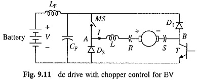
Motoring Operation:
For motoring operation MS is kept closed. Transistor switch T is operated at a constant frequency with variable on time to obtain variable dc voltage for starting and speed control. When T is on, the current flows through the source, LF, MS, L,R, armature, S and T. When T is off, the armature current freewheels through S, D1, MS, L and R.
Regenerative Braking Operation:
For regenerative braking operation MS is kept open and motor armature is reversed with the help of the reversing switch RS making B positive with respect to A. When T is on, the armature current builds up through the path consisting of T, D2 and L. When T is off, the armature current flows against the battery voltage through the path consisting of D1, LF, battery, D2 and L and the energy feedback is utilized to charge the battery.
The drive is operated with closed-loop current control. As the torque is directly proportional to the current, this gives closed-loop torque control. By appropriately controlling the torque the driver sets the vehicle speed at a desired value. The chopper drive of Fig. 5.44 is also used in EV.
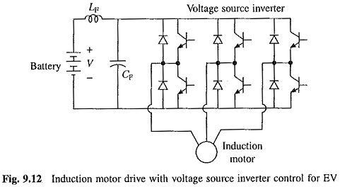
Figure 9.12 shows the induction motor drive for Battery Powered Vehicles. It employs squirrel-cage motor fed from a pulsewidth modulated voltage source inverter. It has inherent capability for regeneration. One has to just reduce the inverter frequency, to make the rotating field speed less than the rotor speed for the operation to shift from motoring to regenerative braking. The drive has all the advantages of induction motor. Because of pulsewidth modulation, drive is efficient and the ride smooth.
Solar Powered Electrical Vehicles and Boats:
At present these vehicles and boats are at experimental stage, but their applications are likely to increase. They employ an intermediate battery, and therefore, the supply system is similar to what is shown in Fig. 9.10 (left of terminals A, B). The drives are similar to those shown in Figs. 9.11 and 9.12.