Heat Capacity of Calorimeter:
Heat Capacity of Calorimeter – RF power may be directly converted into heat. Water acts as the load, and RF power may be used to heat an element such as a long transmission line, water being used as a coolant. The RF power may be absorbed directly in the calorimeter fluid.
The system should have no RF leakage either by radiation or through lossy joints.
Important Features
- All the RF power should be converted into heat and none allowed to leak through radiation.
- No heat should be allowed to radiate from the fluid
The power radiated is given by the relation.
![]()
where
- m = mass, flow gm/s
- sp = specific heat, calories per gm °C
- Δt = temperature rise
- P = power, in W.
Alternatively, the relationship between temperature rise and power dissipated may be established by dissipating a known amount of ac (50 Hz) or dc power in the calorimeter system.
Figure 20.5 is a diagram for measurement of power in a lossy cable using the calorimetric method. In this figure, thermometers are used for measuring the difference in temperature.
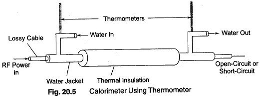
As in the bolometer method of power measurement, the RF portion of the calorimeter system must be designed to provide a proper transformation of impedance. This is usually done by a tapered section.
The length of the cable should be sufficient to provide an attenuation of 10 db or more at the operating frequency, so that the reflected wave will be down by 20 dbs, corresponding to 100 W of power. Thus, the load virtually absorbs almost all the RF power. The cable is available with a standard impedance of 50 Ω, and hence there is no problem of impedance matching. The water acts as the load and directly absorbs the power from the source.
Another arrangement used is the co-axial system, illustrated in Fig. 20.6.
Here, the RF power is absorbed in a water filled section of line. The water serves as a lossy dielectric that absorbs the power because of its high power factor and at the same time functions as the calorimeter fluid.
An impedance match between the section of the co-axial line having an air dielectric and the portion having a water dielectric is provided by the tapered section of titanium dioxide. The material has a dielectric constant very close to that of water (approximately 80) and is ideally suited to match air to water.
The temperature difference between the incoming and outgoing water is measured with a thermopile instead of thermometers, as in Fig. 20.6.
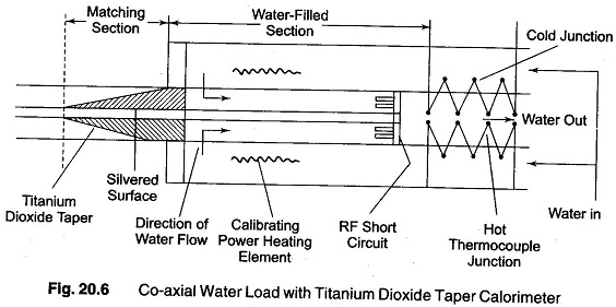
The thermopiles consist of a succession of thermocouple junctions connected in series, as shown in Fig. 20.6, with alternate junctions placed in the incoming (cold) and outgoing (hot) fluid.
A thermopile mounted in this way responds to the difference in temperature between the hot and cold fluids and has a greater sensitivity than does a single hot and cold junction.
Calibration is carried out using dc or 50 Hz power. This consists of an auxiliary heater directly immersed in the flow system. Calibration is carried out by observing the thermopile response produced by the dissipation of a known amount of 50 Hz or dc power in the heater.