IC 565 PLL | Pin Diagram | Block Diagram:
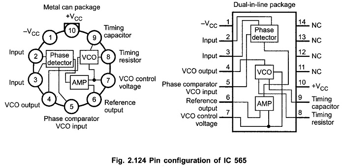
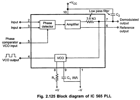
IC 565 PLL is available in a 14 pin DIP package and 10 pin metal can package. Fig. 2.124 shows 14-pin package configuration for IC 565 and Fig. 2.125 shows the block diagram for IC 565.
IC 565 Pin Diagram:
IC 565 Pll Block Diagram:
The block diagram of IC 565 PLL consists of phase detector, amplifier, low pass filter and VCO. As shown in the block diagram the phase locked feedback loop is not internally connected. Therefore, it is necessary to connect output of VCO (pin 4) to the phase comparator input (pin 5), externally. In frequency multiplication applications a digital frequency divider is inserted into the loop i.e. between pin 4 and pin 5.
The centre frequency of the PLL is determined by the free-running frequency of the VCO and it is given as,

where R1 and C1 are an external resistor and a capacitor connected to pins 8 and 9, respectively. The values of R1 and C1 are adjusted such that the free running frequency will be at the centre of the input frequency range. The value of R1 is restricted from 2kΩ to 20 kΩ but a capacitor can have any value. A capacitor C2 connected between pin 7 and the positive supply (pin 10) forms a first order low pass filter with an internal resistance of 3.6 kΩ. The value of filter capacitor C2 should be large enough to eliminate possible oscillations in the VCO voltage.
The lock range and capture range for IC 565 PLL are given by the following equations :
![]()
where
![]()
and
![]()
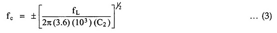
where C2 is in farads.
From equation 2 we can notice that lock range increases with an increase in input voltage but decreases with increase in supply voltage. The two inputs (pin 2 and pin 3) to the phase detector allows direct coupling of an input signal, provided that there is no dc voltage difference between the pins and, the dc resistances seen from pins 2 and 3 are equal. A reference voltage at pin 6 is approximately equal to the dc voltage of the demodulated output at pin 7. This reference voltage may be used as comparator input in applications like frequency shift keying.