Location of Reactors in Power System:
Short circuit current limiting Location of Reactors in Power System may be connected
-
in series with each generator
-
in series with each feeder and
-
in bus-bars.
No definite statement can be given as to which one of the above locations is preferable; each installation has its own particular demands which must be carefully considered before a choice of Location of Reactors in Power System can be made.
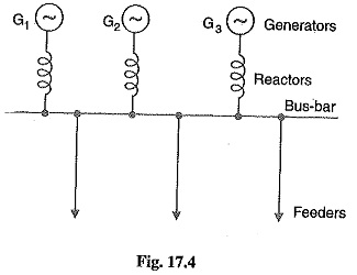
1.Generator Reactors:
When the reactors are connected in series with each generator, they are known as generator reactors (see Fig. 17.4). In this case, the reactor may be considered as a part of leakage reactance of the generator ; hence its effect is to protect the generator in the case of any short-circuit beyond the reactors.
Disadvantages
- There is a constant voltage drop and power loss in the Location of Reactors in Power System even during normal operation.
- If a bus-bar or feeder fault occurs close to the bus-bar, the voltage at the bus-bar will be reduced to a low value, thereby causing the generators to fall out of step.
- If a fault occurs on any feeder, the continuity of supply to other is likely to be affected.
Due to these disadvantages and also since modern power station generators have sufficiently large leakage reactance to protect them against short-circuit, it is not a common practice to use separate reactors for the generators.
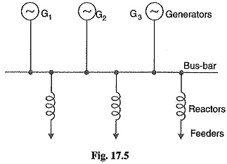
2. Feeder Reactors:
When the reactors are connected in series with each feeder, they are known as feeder reactors (see Fig. 17.5). Since most of the short-circuits occur on feeders, a large number of reactors are used for such circuits. Two principal advantages are claimed for feeder Location of Reactors in Power System. Firstly, if a fault occurs on any feeder, the voltage drop in its reactor will not affect the bus-bars voltage so that there is a little tendency for the generator to lose synchronism. Secondly, the fault on a feeder will not affect other feeders and consequently the effects of fault are localized.
Disadvantages
- There is a constant power loss and voltage drop in the reactors even during normal opera
- If a short-circuit occurs at the bus-bars, no protection is provided to the generators. However, this is of little importance because such faults are rare and modern generators have considerable leakage reactance to enable them to withstand short-circuit across their terminals
- If the number of generators is increased, the size of feeder reactors will have to be increased to keep the short-circuit currents within the ratings of the feeder circuit breakers.
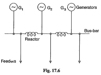
3. Bus-bar reactors:
The above two methods of locating reactors suffer from the disadvantage that there is considerable voltage drop and power loss in the Location of Reactors in Power System even during normal operation. This disadvantage can be overcome by locating the reactors in the bus-bars. There are two methods for this purpose, namely ; Ring system and Tie-Bar system.
(i) Ring system: In this system, bus-bar is divided into sections and these sections are connected through reactors as shown in Fig. 17.6. Generally, one feeder is fed from one generator only. Under normal operating conditions, each generator will supply its own section of the load and very little power will be fed by other generators. This results in low power loss and voltage drop in the reactors. However, the principal advantage of the system is that if a fault occurs on any feeder, only one generator (to which the particular feeder is connected) mainly feeds the fault current while the current fed from other generators is small due to the presence of Location of Reactors in Power System. Therefore, only that section of bus-bar is affected to which the feeder is connected, the other sections being able to continue in normal operation. Bus bar
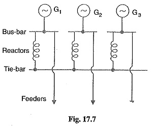
(ii) Tie-Bar system: Fig. 17.7 shows the tie-bar system. Comparing the ring system with tie-bar system, it is clear that in the tie-bar system, there are effectively To bar two reactors in series between sections so that Location of Reactors in Power System must have approximately half the reactance of those used in a comparable ring system. Another advantage of tie-bar system is that additional generators may be connected to the system without requiring changes in the existing reactors. However, this system has the disadvantage that it requires an additional bus-bar i.e. the tie-bar.
Steps for Symmetrical Fault Calculations:
It has already been discussed that 3-phase short-circuit faults result in symmetrical fault currents i.e. fault currents in the three phases are equal in magnitude but displaced 120° electrical from one another. Therefore, problems involving such faults can be solved by considering one phase only as the same conditions prevail in the other two phases. The procedure for the solution of such faults involves the following steps :
- Draw a single line diagram of the complete network indicating the rating, voltage and percentage reactance of each element of the network.
- Choose a numerically convenient value of base kVA and convert all percentage reactances to this base value.
- Corresponding to the single line diagram of the network, draw the reactance diagram showing one phase of the system and the neutral. Indicate the % reactances on the base kVA in the reactance diagram. The transformer in the system should be represented by a reactance in series.
- Find the total % reactance of the network upto the point of fault. Let it be X%.
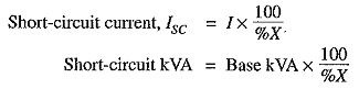
- Find the full-load current corresponding to the selected base kVA and the normal system voltage at the fault point. Let it be I.
- Then various short-circuit calculations are :