Decentralized Control System Definition and Techniques
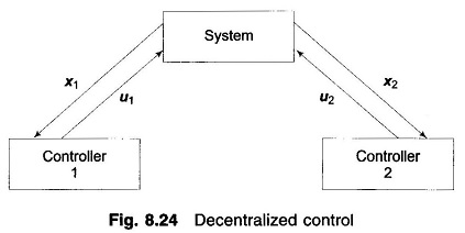
Decentralized Control System Definition and Techniques: Decentralized Control System - In view of the large size of a modern power system, it is virtually impossible to implement either the classical or the modern LFC algorithm…
Comments Off on Decentralized Control System Definition and Techniques
December 6, 2016