Stereo FM Multiplex Reception:
Assuming there have been no losses or distortion in transmission, the demodulator output in a Stereo FM Multiplex Reception, tuned to a stereo transmission, will be exactly as shown in Figure 5-10. Increasing in frequency, the signal components will therefore be sum channel (L + R), 19-kHz subcarrier, the lower and upper sidebands of the difference channel (L — R), and finally the optional SCA (subsidiary communication authorization – telemetry, facsimile, etc.) signal, frequency-modulating a 67-kHz subcarrier. Figure 6-43 shows how these signals are separated and reproduced.
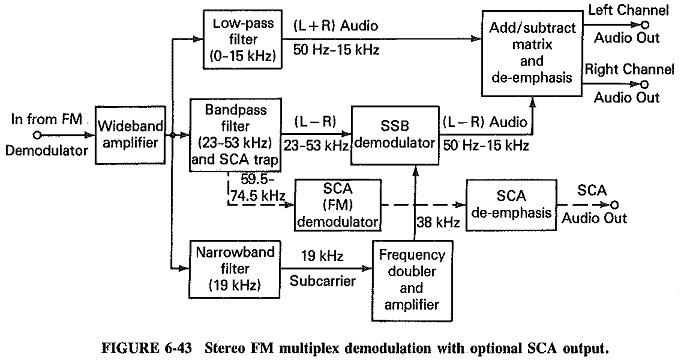
As shown in this block diagram, the process of extracting the wanted information is quite straightforward. A low-pass filter removes all frequencies in excess of 15 kHz and has the sum signal (L + R) at its output. In a monaural receiver, this would be the only output processed further, through a de-emphasis network to audio amplification. The center row of Figure 6.43 shows a bandpass filter selecting the sidebands which correspond to the difference signals (L — R) and also rejecting the (optional) SCA frequencies above 59.5 kHz. The sidebands are fed to a product detector or to a balanced modulator (see Section 6-5 for a discussion of their operation), which also receives the output of the frequency doubler. The doubler converts the transmitted 19-kHz subcarrier, which was selected with a narrowband filter, to the wanted 38-kHz carrier signal, which is then amplified. It will be recalled that the subcarrier had been transmitted at a much reduced amplitude. The two inputs to the SSB demodulator result in this circuit’s producing the wanted difference signal (L — R) when fed to the matrix along with (L + R), produces the left channel from an adder and the right channel from a subtractor. After de-emphasis, these are ready for further audio amplification. Finally the SCA signal is selected, demodulated, also de-emphasized, and produced as a separate audio output.
FM Demodulator Comparison:
The slope detectors single or balanced are not used in practice. They were described so that their disadvantages could be explained, and also as an introduction to practical discriminators. The Foster-Seeley discriminator is very widely used in practice, especially in Stereo FM Multiplex Reception, wideband or narrowband. It is also used in satellite station receivers, especially for the reception of TV carriers.
The ratio detector is a good FM demodulator, also widely used in practice, especially in TV receivers, for the sound section, and sometimes also in narrowband FM radio receivers. Its advantage over the discriminator is that it provides both limiting and a voltage suitable for AGC, while the main advantage of the discriminator is that it is very linear. Thus, the discriminator is preferred in situations in which linearity is an important characteristic (e.g., high-quality Stereo FM Multiplex Reception), whereas the ratio detector is preferred in applications in which linearity is not critical, but component and price savings are (e.g., in TV receivers).
It may be shown that, under critical noise conditions, even the discriminator is not the best FM demodulator. Such conditions are encountered in satellite station receivers, where noise reduction may be achieved by increasing signal strength, receiver sensitivity, or receiver antenna size. Since each of these can be an expensive solution, demodulator noise performance does become very significant. In these circumstances, so-called threshold extension demodulators are preferred, such as the FM feedback demodulator or the phase-locked loop demodulator.