Variable Frequency Control of Multiple Synchronous Motors:
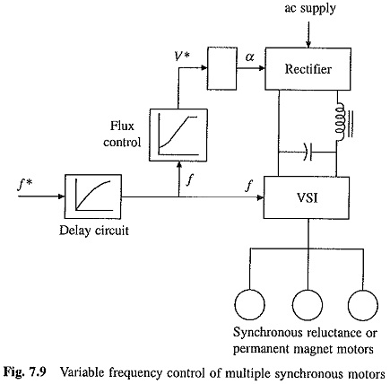
A drive operating in true Variable Frequency Control of Multiple Synchronous Motors is shown in Fig. 7.9. Frequency command f* is applied to a voltage source inverter through a delay circuit so that rotor speed is able to track the changes in frequency.
A flux control block changes stator voltage with frequency to maintain a constant flux below rated speed and a constant terminal voltage above rated speed. This scheme is commonly used for the control of multiple synchronous reluctance or permanent magnet motors in fiber spinning, textile and paper mills where accurate speed tracking between the motors is required.
Synchronous Motor Variable Speed Drives:
Variable Frequency Control:
Synchronous speed (Eq. (7.3)) is directly proportional to frequency. Motor speed can be controlled by varying the frequency. As in case of an induction motor, constant flux operation below base speed is achieved by operating the motor with a constant (V/f) ratio; which is increased at low speeds to compensate for the stator resistance drop.
According to Eqs. (7.4), (7.10) and (7.11), for all types of synchronous motors this gives operation with a constant pull-out torque. Rated voltage is reached at the base speed. For higher speeds, the machine is operated at a rated terminal voltage and Variable Frequency Control of Multiple Synchronous Motors, and the pull-out torque decreases with an increase in frequency.
Modes of Variable Frequency Control:
Variable Frequency Control of Multiple Synchronous Motors may employ any of the two modes:
(i) true synchronous mode or
(ii) self-controlled mode, also known as self-synchronous mode.
In true synchronous mode, the stator supply frequency is controlled from an independent oscillator. Frequency from its initial to the desired value is changed gradually so that the difference between synchronous speed and rotor speed is always small. This allows rotor speed to track the changes in synchronous speed. When the desired synchronous speed (or frequency) is reached, the rotor pulls into step, after hunting oscillations. Variable Frequency Control of Multiple Synchronous Motors control not only allows the speed control, it can also be used for smooth starting and regenerative braking, as long as it is ensured that the changes in frequency are slow enough for rotor to track changes in synchronous speed. A motor with damper winding is used for pull-in to synchronism.
In self-control mode, the stator supply frequency is changed so that synchronous speed is the same as rotor speed. This ensures that rotor runs at synchronous speed for all operating points. Consequently, rotor cannot pull-out of step and hunting oscillations are eliminated. For such applications, the motor may not require a damper winding.
In self-control mode, the stator supply frequency is changed in proportion to the rotor speed so that the rotating field produced by the stator always moves at the same speed as the rotor (or rotor field). Since, the voltage induced in the stator phase has a frequency proportional to rotor speed, self-control can be realized by making the stator supply frequency to track the frequency of induced voltage. Alternatively sensors can be mounted on the stator to track the rotor position. These sensors are called rotor position sensors. The frequency of signals generated by these sensors is proportional to rotor speed. Hence, the stator supply frequency can be made to track the frequency of these signals.