Mesh Analysis Equation:
Mesh Analysis Equation and nodal analysis are two basic important techniques used in finding solutions for a network. The suitability of either mesh or nodal analysis to a particular problem depends mainly on the number of voltage sources or current sources. If a network has a large number of voltage sources, it is useful to use mesh analysis; as this analysis requires that all the sources in a circuit be voltage sources. Therefore, if there are any current sources in a circuit they are to be converted into equivalent voltage sources, if, on the other hand, the network has more current sources, nodal analysis is more useful.
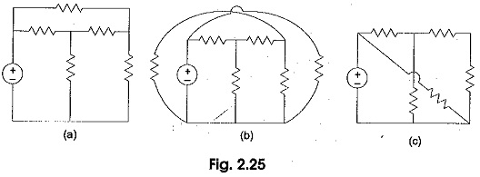
Mesh Analysis Equation is applicable only for planar networks. For non-planar circuits mesh analysis is not applicable. A circuit is said to be planar, if it can be drawn on a plane surface without crossovers. A non-planar circuit cannot be drawn on a plane surface without a crossover.
Figure 2.25 (a) is a planar circuit. Figure 2.25 (b) is a non-planar circuit and Fig. 2.25 (c) is a planar circuit which looks like a non-planar circuit. It has already been discussed that a loop is a closed path. .A mesh is defined as a loop which does not contain any other loops within it. To apply Mesh Analysis Equation, our first step is to check whether the circuit is planar or not and the second is to select mesh currents. Finally, writing Kirchhoff’s voltage law equations in terms of unknowns and solving them leads to the final solution.
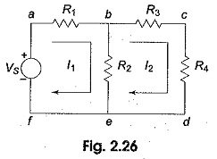
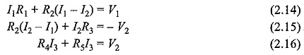
Observation of the Fig. 2.26 indicates that there are two loops abefa, and bcdeb in the network. Let us assume loop currents I1 and I2 with directions as indicated in the figure. Considering the loop abefa alone, we observe that current I1 is passing through R1, and (I1 — I2) is passing through R2. By applying Kirchhoff’s voltage law, we can write
![]()
Similarly, if we consider the second mesh bcdeb, the current I2 is passing through R3 and R4, and (I2 —I1) is passing through R2. By applying Kirchhoff’s voltage law around the second mesh, we have
![]()
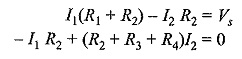
By rearranging the above equations, the corresponding mesh current equations are
By solving the above equations, we can find the currents I1 and I2. If we observe Fig. 2.26, the circuit consists of five branches and four nodes, including the reference node. The number of mesh currents is equal to the number of mesh equations.
And the number of equations = branches — (nodes — 1). In Fig. 2.26, the required number of mesh currents would be 5 — (4 —1) = 2.
In general, if we have B number of branches and N number of nodes including the reference node then the number of linearly independent mesh equations M= B — (N—1).
Mesh Equations By Inspection Method
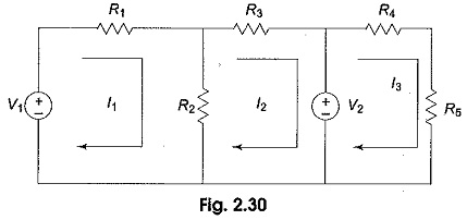
The mesh equations for a general planar network can be written by inspection without going through the detailed steps. Consider a three mesh networks as shown in Fig. 2.30.
The loop equations are
Reordering the above equations, we have
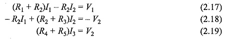
The general mesh equations for three mesh resistive network can be written as
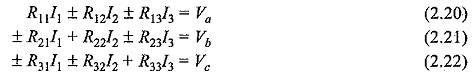
By comparing the Eqs 2.17, 2.18 and 2.19 with Eqs 2.20, 2.21, and 2.22 respectively, the following observations can be taken into account.
- The self resistance in each mesh.
- The mutual resistances between all pairs of meshes and
- The algebraic sum of the voltages in each mesh.
The self resistance of loop 1,R11= R1+R2, is the sum of the resistances through which I1 passes.
The mutual resistance of loop 1,R12 = – R2, is the sum of the resistances common to loop currents I1 and I2. If the directions of the currents passing through the common resistance are the same, the mutual resistance will have a positive sign; and if the directions of the currents passing through the common resistance are opposite then the mutual resistance will have a negative sign.
Va = V1 is the voltage which drives loop one. Here, the positive sign is used if the direction of the current is the same as the direction of the source. If the current direction is opposite to the direction of the source, then the negative sign is used.
Similarly, R22=(R2+R3) and R33=R4+R5 are the self resistances of loops two and three, respectively. The mutual resistances R13=0,R32=0 are the sums of the resistances common to the mesh currents indicated in their subscripts.
Vb=-V2,Vc=V2 are the sum of the voltages driving their respective loops.