Thermistor Operation:
The word thermistor is a combination of thermal and resistor. A thermistor is a resistor with definite thermal characteristics. Most thermistors have a negative temperature coefficient (NTC), but positive temperature coefficient (PTC) devices are also available. Thermistor Operation are widely applied for measurement and control of temperature, liquid, level, gas flow, etc.
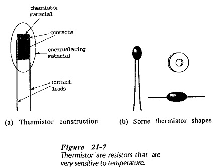
Silicon and germanium are not normally used for thermistor manufacture, because larger and more predictable temperature coefficients are available with metallic oxides. Various mixtures of manganese, nickel, cobalt, copper, iron, and uranium are pressed into desired shapes and sintered (or baked) at high temperature to form thermistors. Electrical connections are made either by including fine wires during the shaping process, or by silvering the surfaces after sintering, [see Fig. 21-7(a)]. Thermistors are made in the shape of beads, probes, discs, washers, etc. [Fig. 21-7(b)]. Beads may be glass-coated or enclosed in evacuated or gas-filled glass envelopes for protection against corrosion.
Characteristics and Specifications:
The typical Thermistor Operation resistance/temperature characteristic in Fig. 21-8 shows that the device resistance (R) decreases substantially when its temperature is raised. At 0°C, R ≈ 1.5 kΩ; and at 60°C, R ≈ 70 Ω. Current flow through a thermistor causes power dissipation that can raise its temperature and change its resistance. This could introduce errors in the thermistor application, so device currents are normally kept to a minimum.
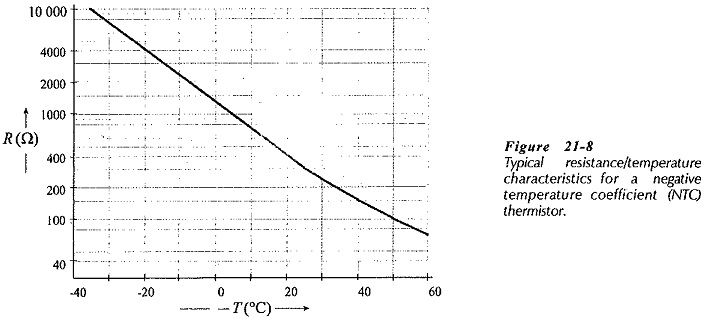
Figure 21-9 shows partial specifications for two thermistors with widely differing resistance values. Both devices have the resistance specified at 25°C as the zero power resistance. This, of course, means that there must be zero power dissipation in the thermistor to give this resistance value. The dissipation constant is the device power dissipation that can raise its temperature through 1°C. The dissipation constant in both cases is specified as 1 mW/°C in still air, and 8 mW/°C in moving liquid. Thus, a thermistor located in still air conditions could have its temperature increased by 1°C if it has 1 mW of power dissipation.
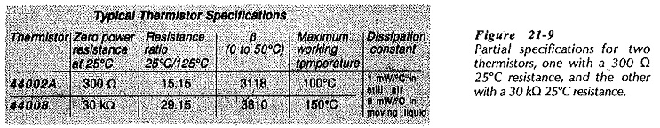
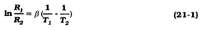
An indication of how much the thermistor resistance changes is given by the resistance ratio at 25/125°C. Clearly, with this ratio specified as 15.15, the resistance at 25°C is divided by 15.15 to determine the resistance at 125°C. Note that both devices have maximum working temperatures listed. The resistance change with temperature is also defined by the constant Beta (β), this time for the range 0°C to 50°C. This constant is used in an equation that relates resistance values at different temperatures:
Applications:
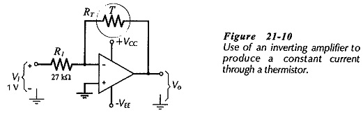
Figure 21-10 shows a thermistor connected as a feedback resistor in an inverting amplifier circuit. (Note the device circuit symbol.) In this case, the thermistor is supplied with a constant current determined by R1 and Vi. The output voltage is directly proportional to the thermistor resistance, and so Vo varies with temperature change.
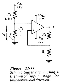
The circuit in Fig. 21-11 illustrates how a Thermistor Operation can be used for triggering a Schmitt circuit at a predetermined temperature. This could be air temperature, or the temperature of a liquid, or perhaps the temperature of some type of heating appliance. When the thermistor resistance (RT) is increased to by the device temperature decrease, the Schmitt input voltage is raised to the upper trigger point, causing the output to switch negatively.