Pole Amplitude Modulation Induction Motor:
Pole changing method as already discussed allows a change of speed by a factor 2. In some applications, speed change is required only by a small amount, e.g. some fan and pump drives require speed reduction to reduce power output at the most to half of rated. Since, torque is proportional to speed squared in a fan drive, power is proportional to (speed)3. Half of rated power is obtained when speed is reduced approximately by 20%. Such a small change in speed is possible by Pole Amplitude Modulation Induction Motor.
The mmf distribution in air-gap owing to stator winding of a three-phase induction motor may be written generally as
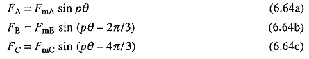
where θ is the mechanical angle.
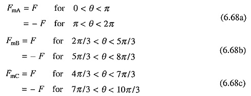
In an ordinary induction motor, the amplitudes of mmfs FmA, FmB and FmC, are constant and equal. In method under discussion, amplitudes are varied (or modulated) according to the rule:
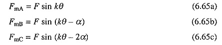
theoretically k and α may have any values.
Substitution from Eq. (6.65) into (6.64) yields
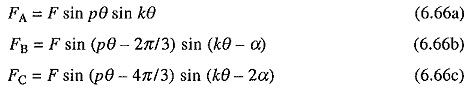
which may be written as
![]()
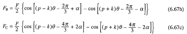
Thus, Pole Amplitude Modulation Induction Motor of mmfs in a three-phase machine having p poles, produces two sets of three-phase mmfs with (p – k) and (p + k) poles. Since, two sets of poles will produce torques in opposite directions, one of them must be suppressed. This can be achieved by choosing the value of α either 2π/3 or –2π/3. From Eq. (6.67) it is evident that modified pole numbers will be (p + k) in former and (p – k) in the latter, as other pole system produces co-phasal mmfs which do not produce any average torque.
Usually value of k, which is known as modulation cycle, is made unity. Even then it is very difficult to implement the modulation law of Eqs. (6.66) because of its sinusoidal nature. It can, however, be simplified as
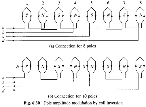
Modulating function for phase A is shown in Fig. 6.29(a). Sinusoidal law of modulation thus has been approximated by a rectangular ac wave. It means that for change in pole number current through the later half of coils in each phase is reversed. This law is known as Coil Inversion. Fig. 6.30 shows implementation of this law for a 8-pole stator. With current direction shown in Fig. 6.30(a), machine operates with 8-poles. Reversal of coil group c-d changes the number of poles to 10 as shown in Fig. 6.30(b). Here also the required direction of currents through coils can be obtained by connecting coil groups a-b and c-d either in series or parallel. By proper choice of series and parallel connections on one hand and delta and star on the other hand, constant torque, constant power and variable torque operations can be obtained.
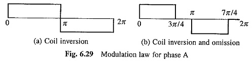
Another simple law of Pole Amplitude Modulation Induction Motor, known as coil inversion and omission, is shown in Fig. 6.29(b) for phase A. This will however require that the connections are brought out for three coil groups for each phase. By drawing a figure similar to Fig. 6.30, it can be shown that the Pole Amplitude Modulation Induction Motor of a 8-pole machine gives 6-poles.
As pole-systems are not alternating along the periphery, these motors in modified connection suffer from harmonic currents and voltages, and have lower power factor and efficiency than pole changing motors described in the earlier section. They find applications in fan, blower and pump drives.