Linear Integrated Circuits

Instrumentation Amplifier or Data Amplifier

Instrumentation Amplifier or Data Amplifier: Instrumentation Amplifier – Many industrial systems, consumer systems and process control systems require a precise measurement of the physical quantities like temperature, pressure, humidity, weight etc. A sugar factory requires a measurement of flow, level and temperature of juice. The plastic furnaces require precise measurement of the temperature. The dairy […]

Instrumentation Amplifier or Data Amplifier Read More »

Summing Differentiator Circuit

Summing Amplifier Circuit

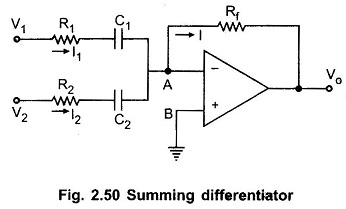
Summing Differentiator Circuit: Summing Differentiator Circuit – Similar to the summing integrator, summing can be obtained using the basic differentiator Circuit. It can be obtained by applying more than one input to the basic differentiator Circuit as shown in the Fig. 2.50. The node B is grounded, hence potential of A is also zero. So

Summing Differentiator Circuit Read More »

Practical Differentiator

Practical Differentiator

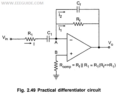
Practical Differentiator: The noise and stability at high frequency can be corrected, in the practical differentiator circuit using the resistance R1 in series with C1 and the capacitor Cf in parallel with resistance Rf. The circuit is shown in the Fig. 2.49. The resistance Rcomp is used for bias compensation. Analysis of the Practical Differentiator:

Practical Differentiator Read More »

Summing Integrator Circuit

Summing Integrator Circuit

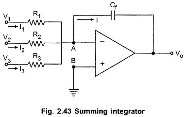
Summing Integrator Circuit: Many useful circuits can be designed using the basic integrator circuit. One of such useful circuits is the Summing Integrators. It can be obtained by applying more than one input to the basic integrator circuit. The Summing Integrator Circuit is shown in the Fig. 2.43. The node B is ground hence node

Summing Integrator Circuit Read More »

Op Amp Integrator Circuit

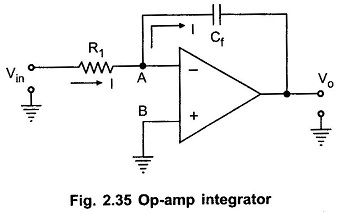
Op Amp Integrator Circuit: In an Op Amp Integrator Circuit, the output voltage is the integration of the input voltage. The integrators circuit can be obtained without using active devices like op-amp, transistors etc. in such a case an integrator is called passive integrators. While an integrators using an active devices like op-amp is called

Op Amp Integrator Circuit Read More »

Summing Amplifier

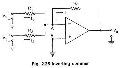
Summing Amplifier: As the input impedance of an op-amp is extremely large, more than one input signal can be applied to the inverting amplifier. Such circuit gives the addition of the applied signals at the output. Hence it is called Summer or adder circuit. Depending upon the sign of the output, the Summing Amplifier circuits

Summing Amplifier Read More »

Voltage Follower Op Amp

Voltage Follower Op Amp

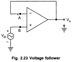
Voltage Follower Op Amp: A circuit in which the output voltage follows the input voltage is called voltage follower circuit. The Voltage Follower Op Amp circuit diagram is shown in the Fig. 2.23. The node B is at potential Vin. Now node A is also at the same potential as B i.e. Vin. Now node A is

Voltage Follower Op Amp Read More »

Non Inverting Operational Amplifier

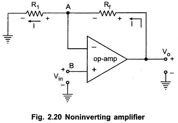
Non Inverting Operational Amplifier: An amplifier which amplifies the input without producing any phase shift between input and output is called Noninverting Amplifier. The basic circuit diagram of a Non Inverting Operational Amplifier is shown in the Fig. 2.20. The input is applied to the noninverting input terminal of the op-amp. Let us derive the

Non Inverting Operational Amplifier Read More »

Scroll to Top