Sphere Gaps are used to measure Voltage Measurement:
Sphere Gaps are used to measure Voltage Measurement – A uniform field spark gap will always have a sparkover voltage within a known tolerance under constant atmospheric conditions. Hence a spark gap can be used for measurement of the peak value of the voltage, if the gap distance is known. A sparkover voltage of 30 kV (peak) at 1 cm spacing in air at 20°C and 760 ton pressure occurs for a Sphere Gap Measurement or any uniform field gap. But experience has shown that these measurements are reliable only for certain gap configurations.
Normally, only sphere gaps are used for voltage measurements. In certain cases uniform field gaps and rod gaps are also used, but their accuracy is less. The spark gap breakdown, especially the sphere gap breakdown, is independent of the voltage waveform and hence is highly suitable for all types of waveforms from d.c. to impulse voltages of short rise times (rise time ≥ 0.5 μs). As such, Sphere Gaps are used to measure radio frequency a.c. voltage peak measurements also (up to 1 MHz).
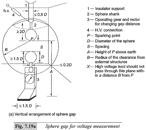
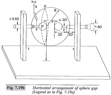
Sphere Gap Measurement can be arranged either (i) vertically with lower sphere grounded, or (ii) horizontally with both spheres connected to the source voltage or one sphere grounded. In horizontal configurations, it is generally arranged such that both spheres are symmetrically at high voltage above the ground. The two spheres used are identical in size and shape. The schematic arrangement is shown in Figs 7.19a and 7.19b. The voltage to be measured is applied between the two spheres and the distance or spacing S between them gives a measure of the sparkover voltage.
A series resistance is usually connected between the source and the sphere gap to (i) limit the breakdown current, and (ii) to suppress unwanted oscillations in the source voltage when breakdown occurs (in case of impulse voltages). The value of the series resistance may vary from 100 to 1000 kilo ohms for a.c. or d.c. voltages and not more than 500 Ω in the case of impulse voltages.
In the case of a.c. peak value and d.c. voltage measurements, the applied voltage is uniformly increased until sparkover occurs in the gap. Generally, a mean of about five breakdown values is taken when they agree to within ± 3%.
In the case of impulse voltages, to obtain 50% flashover voltage, two voltage limits, differing by not more than 2% are set such that on application of lower limit value either 2 or 4 flashovers take place and on application of upper limit value 8 or 6 flashovers take place respectively. The mean of these two limits is taken as 50% flashover voltage. In any case, a preliminary sparkover voltage measurement is to be made before actual measurements are made.
The flashover voltage for various gap distances and standard diameters of the Sphere Gap Measurement used are given in Tables 7.3 and 7.4 respectively. The values of sparkover voltages are specified in BS : 358, IEC Publication 52 of 1960 and IS: 1876 of 1962. The clearances necessary are shown in Figs 7.19a and 7.19b for measurements to be within ± 3%.
Sphere Gap Construction and Assembly:
Sphere gaps are made with two metal spheres of identical diameters D with their shanks, operating gear, and insulator supports (Fig. 7.19a or b). Sphere Gaps are used to measure are generally made of copper, brass, or aluminium; the latter is used due to low cost. The standard diameters for the spheres are 2, 5, 6.25, 10, 12.5, 15, 25, 50, 75, 100, 150, and 200 cm. The spacing is so designed and chosen such that flashover occurs near the sparking point P. The spheres are carefully designed and fabricated so that their surfaces are smooth and the curvature is uniform.
The radius of curvature measured with a spherometer at various points over an area enclosed by a circle of 0.3 D around the sparking point should not differ by more than ± 2% or the nominal value. The surface of the sphere should be free from dust, grease, or any other coating. The surface should be maintained clean but need not be polished. If excessive pitting occurs due to repeated sparkovers, they should be smoothened.
The dimensions of the shanks used, the grading ring used (if necessary) with spheres, the ground clearances, etc. should follow the values indicated in Figs 7.19a and 7.19b and Table 7.5. The high voltage conductor should be arranged such that it does not affect the field configuration. Series resistance connected should be outside the shanks at a distance 2D away from the high voltage sphere or the sparking point P.
Irradiation of Sphere Gap Measurement is needed when measurements of voltages less than 50 kV aremade with Sphere Gap Measurement of 10 cm diameter or less. The irradiation may be obtained from a quartz tube mercury vapour lamp of 40 W rating.


