Motor Design Parameters:
Different parts of a load may be coupled through different mechanisms, such as gears, V-belts and crankshaft. These parts may have different speeds and different types of Motions such as rotational and translational. This section presents methods of Motor Design Parameters finding the equivalent moment of inertia (J) of motor-load system and equivalent torque components, all referred to motor shaft.
Loads with Rotational Motion:
Let us consider a motor driving two loads, one coupled directly to its shaft and other through a gear with n and n1 teeth as shown in Fig. 2.4(a). Let the moment of inertia of motor and load directly coupled to its shaft be J0, motor speed and torque of the directly coupled load be ωm and Tl0 respectively. Let the moment of inertia, speed and torque of the load coupled through a gear be J1, ωm1 and Tl1 respectively. Now,
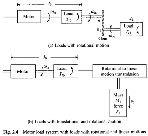
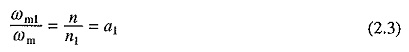
where a1 is the gear tooth ratio.
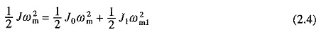
If the losses in transmission are neglected, then the kinetic energy due to equivalent inertia must be the same as kinetic energy of various moving parts. Thus
From Eqs. (2.3) and (2.4)
![]()
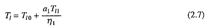
Power at the loads and motor must be the same. If transmission efficiency of the gears be η1, then
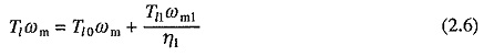
where Tl is the total equivalent torque referred to motor shaft.
From Eqs. (2.3) and (2.6)
If in addition to load directly coupled to the motor with inertia J0 there are m other loads with moment of inertias J1, J2, . . . , Jm and gear teeth ratios of a1, a2, . . . am then
![]()
If m loads with torques Tl1, Tl2, . . . , Tlm are coupled through gears with teeth ratios a1, a2, . . . am and transmission efficiencies η1, η2 , . . . , ηm, in addition to one directly coupled, then
![]()
If loads are driven through a belt drive instead of gears, then, neglecting slippage, the equivalent inertia and torque can be obtained from Eqs. (2.8) and (2.9) by considering a1, a2, . . . , am each to be the ratios of diameters of wheels driven by motor to the diameters of wheels mounted on the load shaft.
Loads with Translational Motion:
Let us consider a motor driving two loads, one coupled directly to its shaft and other through a transmission system converting rotational motion to linear motion (Fig. 2.4(b)). Let moment of inertia of the Motor Design Parameters and load directly coupled to it be J0, load torque directly coupled to motor be Tl0, and the mass, velocity and force of load with translational motion be M1 (kg), υ1 (m/sec) and F1 (Newtons), respectively.
If the transmission losses are neglected, then kinetic energy due to equivalent inertia J must be the same as kinetic energy of various moving parts. Thus
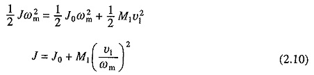
Similarly, power at the motor and load should be the same, thus if efficiency of transmission be η1
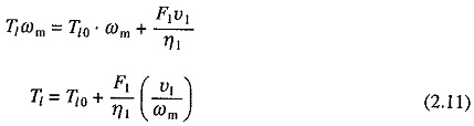
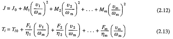
If, in addition to one load directly coupled to the motor shaft, there are m other loads with translational motion with velocities υ1,υ2, . . . υm and masses M1,M2, . . . , Mm, respectively, then
Measurement of Moment of Inertia:
Moment of inertia can be calculated if dimensions and weights of various parts of the load and Motor Design Parameters are known. It can also be measured experimentally by retardation test.
In retardation test, the drive is run at a speed slightly higher than rated speed and then the supply to it is cut off. Drive continues to run due to kinetic energy stored in it and decelerates due to rotational mechanical losses. Variation of speed with time is recorded.
At any speed ωm power P consumed in supplying rotational losses is given by
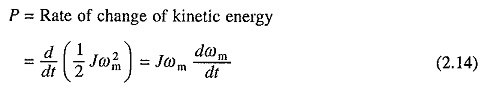
From retardation test dωm/dt at rated speed is obtained. Now drive is reconnected to the supply and run at rated speed and rotational mechanical power input to the drive is measured. This is approximately equal to P. Now J can be calculated from Eq. (2.14). Main problem in this method is that rotational mechanical losses cannot be measured accurately because core losses and rotational mechanical losses cannot be separated. In view of this, retardation test on a dc separately excited motor or a synchronous motor is carried out with field on. Now core loss is included in the rotational loss, which is now obtained as a difference of armature power input and armature copper loss. In case of a wound rotor induction motor, retardation test can be carried out by keeping the stator supply and opening the rotor winding connection.
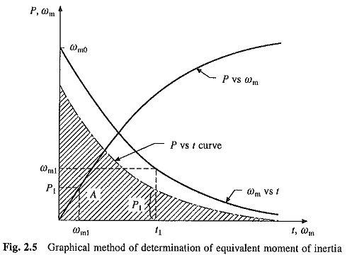
J can be determined more accurately by obtaining speed time curve from the retardation test as above and also rotational losses vs speed plot as shown in Fig. 2.5. Using these two plots, rotational losses vs time plot can be obtained, e.g. for time t1, ωm1 is found from the retardation plot. Then for this speed rotational loss P1 is obtained from the plot of rotational loss vs speed and plotted against t1. Area A enclosed between the rotational loss vs t plot and the time axis (shaded area), is the kinetic energy dissipated during retardation test. If initial speed of the drive during retardation test was ωm0 then
![]()