Stray Capacitance Effects:
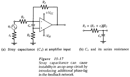
Stray Capacitance Effects (Cs) at the input terminals of an operational amplifier effectively introduces an additional phase-lag network in the feedback loop, (see Fig. 15-17), thus making the op-amp circuit unstable.
Stray capacitance problems can be avoided by good circuit construction techniques that keep the stray to a minimum. The effects of stray capacitance also depend upon the resistor values used in the feedback network. High resistance values make it easier for small stray capacitances to produce phase lag. With low-resistances, small stray capacitances normally have little effect on the circuit stability.
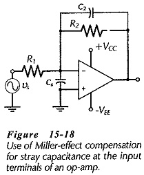
Analysis of an RC phase lag circuit shows that the capacitor voltage lags the input voltage by 45° when the capacitor impedance (Xc) equal the series resistance (R). Also, when Xc = 10 R, the phase lag is approximately 10°, and it is this 10° of additional phase lag that might make the circuit oscillate if its phase margin is already close to the minimum for stability. If the phase margin is known to be large at the frequency where AvB = ACL (the frequency at which the circuit is likely to oscillate), the stray capacitance might be unimportant. Where the phase margin is small, for circuit stability the op-amp input stray capacitance should normally be much less than,
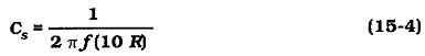
where R is the equivalent resistance in series with the stray capacitance. In Fig. 15-17, R = R3 + (R1 + rs)||R2.
From Eq. 15-4 it is seen that (as already mentioned) the larger resistor values the smaller the stray capacitance that can produce circuit instability. If the signal source is disconnected from the circuit, R becomes equal to (R2 + R3), which is much larger than [R3 + (rs + R1)||R2]. In this situation, extremely small stray capacitance values can make the circuit unstable.
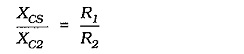
Miller-effect compensation can be used to compensate for stray capacitance at an op-amp input, as shown in Fig. 15-18. To eliminate the phase shift introduced by the stray capacitance the division of the output voltage produced by Cs and C2 in series should be equal to the division produced by R1 and R2. Therefore,
This gives,
![]()
Note that Eq. 15-5 does not allow for rs or R3 in Fig. 15-17. Where rs is not very much smaller than R1, it must be added to R1. Also, resistor R3 could be bypassed with another capacitor to reduce the total series resistance.