Schering Bridge Theory for Three Terminal Measurement:
For two terminal measurements the bridge is grounded at its junction points. The supply transformer, detector, and all the components of the bridge are enclosed in earthed shields. For Schering Bridge Theory for Three Terminal Measurement, it is necessary to avoid stray capacitances, for accurate measurements. Hence, a guard circuit and earthing device (known as Wagner’s earthing device) are used. The bridge is balanced once with the ratio arms and again with the earthing device, alternately, so that no change in balance occurs. This ensures the elimination of stray ground capacitances and coupling. The schematic arrangement of Schering Bridge Theory for Three Terminal Measurement is shown in Fig. 9.17. The arms, containing RY and RWCW are the Wagner earthing device arms. The bridge is first balanced with RA,RB,CN, and CT and later with RV,RW,CN, and CT. The detector is alternately connected to either the earthing device or to the bridge arms A and B. The balance is achieved, when at either position the detector indicates the same null indication.
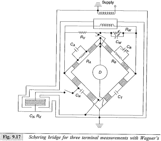
This Schering Bridge Theory for Three Terminal Measurement can be extended to frequencies as high as 500 kHz beyond which the lead lengths and the residual inductances in various arms become too high to achieve proper balance.
Transformer Ratio Arm Bridge:
It is a common practice to use the four arm Wheatstone bridge network for a.c. measurements. In high frequency measurements, the arms with high values of resistances lead to difficulties due to their residual inductances, capacitances, and skin effect. Also, shielding and grounding becomes difficult in large arms. Hence, at high frequencies the transformer ratio arm bridge which eliminate at least two arms are preferred. These bridges are also useful for the measurement of low value of capacitances accurately.
The ratio arm bridges can be either voltage ratio type or current ratio type; the former being used for high frequency low voltage applications.
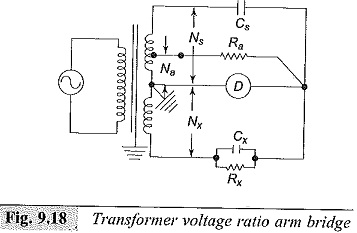
The schematic diagram of a ratio arm bridge (voltage ratio) is given in Fig. 9.18. Assuming ideal transformer conditions, for a null indication of the detector,
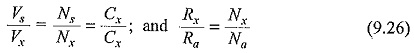
where Cx and Cs are unknown and standard capacitances respectively, Rx and Ra are unknown and standard resistances, and Nx,Na, and Ns are the corresponding turns of the transformer ratio windings.
In practical transformers, the voltage ratio’slightly differs from the turns ratio due to the no load magnetizing current and is also affected by the load current. Therefore, the balance conditions- showb above involve errors. The errors are classified as the ratio and loading errors and are determined separately and compensated for in, the construction. A practical bridge constructed by General Radio Company (USA) has a useful range from a fraction of one pF to about 100 μF and covers a wide range of frequency from 100 Hz to 100 kHz, the accuracy being better than 0.5%.
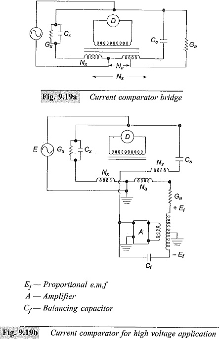
For high voltage applications where sensitive measurements at fixed frequency (at 50 Hz) are required, the current comparator or the current ratio method (Fig. 9.19a) is used. This bridge has the advantage that full voltage is applied across the test capacitor but also has the drawback that a standard conductance has to be built for high voltages. It is difficult to construct a precision conductance suitable for high voltage operation. This disadvantage is overcome by generating a low voltage signal Ef proportional to and in phase with the supply voltage E as shown in the modified Fig. 9.19b. At balance, there is no voltage across the current comparator winding. If the gain of the amplifier (A) is high, that is
![]()
The balance equations of the bridge are
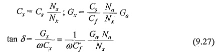
where Cx,Cs,Ns,Na, and Nx are as defined in Eq. (9.26), Gx and Ga are unknown and standard conductances, and Cf is the balancing capacitor.
Detectors in Dielectric Measurements:
Since the measurements cover a large range of frequency, the detectors used in various ranges differ considerably. For d.c. and low frequency measurements, d.c. galvanometer and d.c. amplifiers with a micorammeter are used.
In power frequency a.c. measurements (50 Hz/60 Hz) vibration galvanometers serve as excellent tuned detectors as their bandwidth is quite narrow (±1 to 2 Hz). But often tuned electronic amplifier null detectors are also used.
In the audio frequency range wide band or tuned null detectors are used with a sensitivity better than 10 μV. This consists of a filter, an attenuator, a multistage amplifier using a bridge rectifier with a microammeter. The bandwidth of the detector is from 50 Hz to 50 kHz and is protected from high input signals at off balance position.
Cathode ray oscilloscopes are also used as detectors, if too high a sensitivity is not required.
The selection of the detector depends on the type of bridge circuit used for measurement and the sensitivity required in the particular application.