Induction Regulators:
An induction regulators is essentially a constant voltage transformer, one winding of which can be moved w.r.t. the other, thereby obtaining a variable secondary voltage. The primary winding is connected across the supply while the secondary winding is connected in series with the line whose voltage is to be controlled. When the position of one winding is changed w.r.t the other, the secondary voltage injected into the line also changes. There are two types of Induction Regulators viz. namely
- Single Phase Induction Regulator
- Three Phase Induction Regulator
1.Single Phase Induction Regulator: A single phase induction regulator is illustrated in Fig.15.9. In construction, it is similar to a single phase induction motor except that the rotor is not allowed to rotate continuously but can be adjusted in any position either manually or by a small motor. The primary winding AB is wound on the stator and is connected across the supply line. The secondary winding CD is wound on the rotor and is connected in series with the line whose voltage is to be controlled.
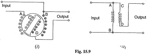
The primary exciting current produces an alternating flux that induces an alternating voltage in the secondary winding CD. The magnitude of voltage induced in the secondary depends upon its position w.r.t. the, primary winding. By adjusting the rotor to a suitable position, the secondary voltage can be varied from a maximum positive to a maximum negative value. In this way, the regulator can add or subtract from the circuit voltage according to the relative positions of the two winding. Owing to their greater flexibility, single phase regulators are frequently used for voltage control of distribution primacy feeders.
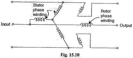
2.Three Phase Induction Regulator: In construction, a 3-phase induction regulator is similar to a 3-phase induction motor with wound rotor except that the rotor is not allowed to rotate continuously but can be held in any position by means of a worm gear. The primary windings either in star or delta are wound on the stator and are connected across the supply. The secondary windings are wound on the rotor and the six terminals are brought out since these windings are to be connected in series with the line whose voltage is to be controlled.
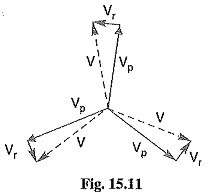
When polyphase currents flow through the primary windings, a rotating field is set up which induces an e.m.f. in each phase of rotor winding. As the rotor is turned, the magnitude of the rotating flux is not changed; hence the rotor e.m.f. per phase remains constant. However, the variation of the position of the rotor will affect the phase of the rotor e.m.f. w.r.t. the applied voltage as shown in Fig. 15.11. The input primary voltage per phase is Vp and the boost introduced by the regulator is Vr. The output voltage V is the vector sum of Vp and Vr. Three phase induction regulators are used to regulate the voltage of feeders and in connection with high voltage oil testing transformers.