Search Results for: mmf

MMF of AC Distributed Winding

MMF of Distributed AC Windings

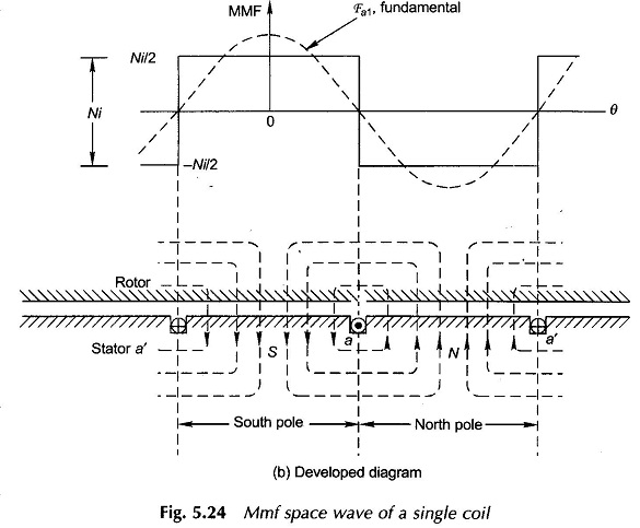
MMF of AC Distributed Winding: It has been seen earlier that the armature what-when-how.comof a practical machine has distributed winding wound for the same number of poles as the field winding. As the armature carries current, the resultant field of its current-carrying coils has the same number of poles as the field winding. Our approach […]

MMF of AC Distributed Winding Read More »

Electrical Braking of Polyphase Induction Motors

Torque-Slip Curves of Polyphase Induction Motor

Electrical Braking of Polyphase Induction Motors: Electrical Braking of Polyphase Induction Motors which consists of different types, namely, Plugging (or Counter-Current Braking) Dynamic (or Rheostatic) Braking Regenerative Braking 1. Plugging (or Counter-Current Braking) Plugging can be achieved in an induction motor merely by reversing two of the three phases which causes a reversal of the

Electrical Braking of Polyphase Induction Motors Read More »

Amplidyne (Rotary Amplifier) – Definition, Construction, Connection Diagram, Workings and Applications

Amplidyne Constructional and Connection Diagram

Amplidyne (Rotary Amplifier) – Definition, Construction, Connection Diagram, Workings and Applications: The amplidyne is a rotary amplifier in which a small amount of power supplied to excite the field is amplified in the generator output. Though the ordinary separately excited generator operated at low flux densities can be used as a power amplifier since the

Amplidyne (Rotary Amplifier) – Definition, Construction, Connection Diagram, Workings and Applications Read More »

Parallel Magnetic Circuit

Parallel Magnetic Circuit: We have seen that a series magnetic circuit carries the same flux and the total mmf required to produce a given quantity of flux is the sum of the mmf’ s for the separate parts. In a Parallel Magnetic Circuit, different parts of the circuit are in parallel. For such circuits the

Parallel Magnetic Circuit Read More »

Difference Between Electric Circuit and Magnetic Circuit

Difference Between Electric Circuit and Magnetic Circuit: A Difference Between Electric Circuit and Magnetic Circuit are shown in Figs. 10.27(a) and (b) respectively. Figure 10.27(a) represents an electric circuit with three resistances connected in series, the dc source E drives the current I through all the three resistances whose voltage drops are V1,V2 and V3. Hence,

Difference Between Electric Circuit and Magnetic Circuit Read More »

Series Magnetic Circuit

Series Magnetic Circuit: A series magnetic circuit is analogous to a series electric circuit. Kirchhoff s laws are applicable to magnetic circuits also. Consider a ring specimen having a magnetic path of l meters, area of cross-section (A)m2 with a mean radius of R meters having a coil of N turns carrying I amperes wound

Series Magnetic Circuit Read More »

Magnetic Circuit Analysis

Magnetic Circuit Analysis: Magnetic Circuit Analysis – The presence of charges in space or in a medium creates an electric field, similarly the flow of current in a conductor sets up a magnetic field. Electric field is represented by electric flux lines, magnetic flux lines are used to describe the magnetic field. The path of

Magnetic Circuit Analysis Read More »

Self Controlled Synchronous Motor Drive

Self Controlled Synchronous Motor Drive: A Self Controlled Synchronous Motor Drive employing a load commutated thyristor inverter is shown in Fig. 7.10. In large power drives wound field synchronous motor is used. Medium power drives also employ permanent magnet synchronous motor. The drive employs two converters, which are termed here as source side converter and

Self Controlled Synchronous Motor Drive Read More »

Scroll to Top