Marker Generator Block Diagram:
Marker Generator – The sweep generator provides a visual display of the characteristics of the circuit or amplifier, but this is inadequate because it does not give any precise information of the frequency on the traced curve. For this, a separate RF generator, known as the Marker generator is used. This generator though essentially an RF signal generator in the VHF and UHF bands, is of much higher accuracy than other signal generators.
The output of the Marker generator is set at the desired frequency within the pass-band of the circuit under test.
As given in Fig. 8.12, the outputs from two generators are mixed together before being applied to the input terminals of the circuit under test.
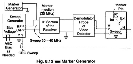
The two signals are heterodyned to produce outputs at the sum and difference of two frequencies. These appear at the detector output and represent the amplitude characteristics of the circuit, because of the limited frequency response of the CRO vertical amplifier, the sum and difference frequency signals are produced when the sweep frequency varies over a wide range. When no difference frequency is produced, no vertical deflection is produced on the screen. However, as the frequency approaches and just crosses the marker frequency, the difference frequency signals which are produced, lie within the pass-band of the vertical amplifier. Thus, they produce a pip on the screen along the trace generated by the low frequency output of the detector. In order to get a sharp pip, a suitable capacitor is shunted across the vertical input terminals of the scope.
Since the pip is produced at the marker frequency, it can be shifted to any point on the response curve by varying the marker generator frequency.
The marker generator, besides providing dial controlled frequency, often has a provision to generate crystal controlled fixed frequency outputs at several important frequencies.
The additional frequency in a generator designed for a CCIR 625 lines system consists of the following.
- 31.4 MHz (Band-edge)
- 31.9 MHz (Trap-frequency)
- 33.4 MHz (Sound IF)
- 34.47 MHz (Colour IF)
- 36.15 MHz (Band centre)
- 38.9 MHz (Picture IF)
- 40.4 MHz (Trap frequency)
- 41.4 MHz (Band-edge)
These birdy-type markers can be switched in, either individually or simultaneously by the use of toggle switches on the front panel.
Sweep Marker Generator:
Sweep and Marker generators were earlier manufactured as separate units. Now the two instruments are combined into a single instrument known as a Sweep Marker generator.
This includes a built-in Marker adder for post-injection of the marker signal. Also provided is a variable dc bias source for feeding a fixed bias to the RF and IF sections of the receiver.
The frequency spectrum covered is in the VHF and UHF band ranges in both manual and auto modes. The RF output is about 0.5 V rms across a 75 Ω with a continuously variable attenuator, up to 50 db or 0 – 60 db in 10 db steps. The marker section provides crystal controlled output at all important frequencies. The output can be internally modulated with a 1 kHz tone when necessary. A demondulator probe, a balun and special cables with matched terminations are the additional accessories.
Wobbluscope:
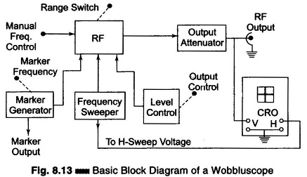
This instrument combines a Sweep generator, a Marker generator, and an oscilloscope, as shown in Fig. 8.13. It is a very useful unit for the alignment of RF, IF and video sections of a TV receiver. It may not have all the features of a high quality sweep generator but is an economical and compact piece of equipment specially designed for TV servicing. The oscilloscope usually has a provision for TV-V (vertical) and TV-H (horizontal) sweep modes. An RF output, down to 1 MHz, is available for video amplifier testing.