Effects of Negative Feedback in Amplifiers:
Decibels of Feedback – Effects of Negative Feedback in Amplifiers can be measured in decibels. A statement that 40 dB of feedback has been applied to an amplifier means that the amplifier gain has been reduced by 40 dB, (that is, by a factor of 100). Thus, 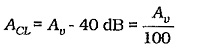
Bandwidth:
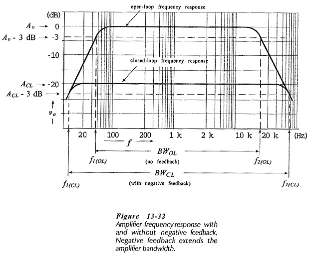
Consider the typical gain-frequency response of an amplifier, as illustrated in Fig. 13-32. Without negative feedback, the amplifier open-loop (Av) gain falls off to its lower 3 dB frequency (f1(OL)), as illustrated. This is usually due to the impedance of bypass capacitors increasing as the frequency decreases. Similarly, the open-loop upper cutoff frequency (f2(OL)) is produced by transistor cutoff, by shunting capacitance, or by a combination of both. As discussed earlier, the circuit open-loop bandwidth is,
![]()
Now look at the typical frequency response for the same amplifier when Effects of Negative Feedback in Amplifiers is used. The closed-loop gain (ACL) is much smaller than the open-loop gain, and ACL does not begin to fall off (at high or low frequencies) until Av (open-loop) falls substantially. Consequently, f1(CL) is much lower than f1(OL), and f2(OL) is much higher than f2(OL). So, the circuit bandwidth with negative feedback (the closed-loop bandwidth) is much greater than the bandwidth without negative feedback.
![]()
From Eq. 13-2,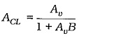
It can be shown that there is a 90° phase shift associated with the open-loop gain at frequencies below f1(OL) and above f2(OL).
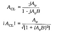
When Av = 1/B,
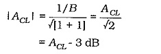
Thus, for a Effects of Negative Feedback in Amplifiers designed to have the widest possible bandwidth, the cutoff frequencies would occur when the open-loop gain falls to the equivalent of 1/B. Thus, f2(CL) occurs when,
![]()
So, for example, the cutoff frequencies for a negative feedback amplifier designed for a closed-loop gain of 100 would occur when the open-loop gain falls to 100. It is seen that,
negative feedback increases amplifier bandwidth.
The upper cutoff frequency for an amplifier is usually greater than 20 kHz, and the lower cutoff frequency is around 100 Hz, or lower. So, f2 ≫ f1, and consequently,![]()
This means that the amplifier bandwidth is essentially equal to the upper cutoff frequency.
Now refer to Fig. 13-32 once again. The amplifier gain multiplied by the upper cutoff frequency is a constant quantity. This is known as the gain-bandwidth product. Therefore,
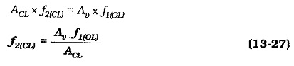
So, the closed-loop upper cut-off frequency for a negative feedback amplifier can be calculated from the open-loop upper cutoff frequency, the open-loop gain, and the closed-loop gain
Harmonic Distortion:
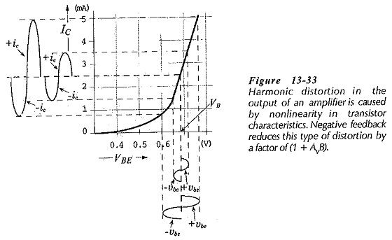
Harmonic Distortion occurs when a transistor or other device is driven beyond the linear range of its characteristics. Figure 13-33 shows the IC/VBE characteristics of a transistor biased to a base-emitter voltage VB. As illustrated, when the base-emitter voltage changes (±vbe) are very small, the collector current changes by equal positive and negative amounts (±ic). When ±vbe is large, the change in ±ic is greater than the change in -ic. This is because of the non-linearity in the IC/VBE characteristics. The result is harmonic distortion(or nonlinear distortion) in the waveform of ic and in the amplifier output.
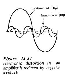
The distorted waveform can be shown to consist of a fundamental frequency waveform and a number of smaller amplitude harmonic components, (see Fig. 13-34). The fundamental waveform is the amplified signal,, or amplifier output voltage (vo), and the harmonics are unwanted voltage components (VH). The harmonic distortion is the rms value of VH expressed as a percentage of the rms value of vo. The harmonics (generated within the feedback loop) are reduced by Effects of Negative Feedback in Amplifiers by a factor of (I + AvB). So that,
So,
negative feedback reduces harmonic distortion.
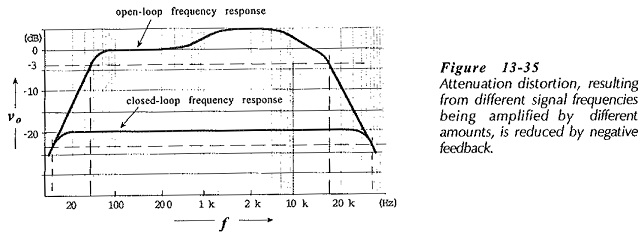
Attenuation Distortion:
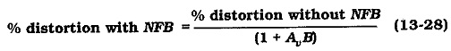
Attenuation distortion occurs when different frequencies are amplified by different amounts. This type of distortion is the result of the amplifier open-loop gain being frequency-dependent, (see Fig. 13-35). When negative feedback is used, the closed-loop gain is a constant quantity largely independent of signal frequency within the circuit bandwidth. Like harmonic distortion, attenuation distortion is reduced by a factor of (1 + AvB) by Effects of Negative Feedback in Amplifiers. Equation 13-28 applies. Thus,
negative feedback reduces attenuation distortion.
Phase Shift:
Input signals to an amplifier go through phase-shifts from the input to the output. The wave forms in Fig. 13-36 show that, in a two-stage circuit, there is a 180° phase shift from vs to vo1, and a further 180° shift from vo1 to vo2. In some cases, an amplifier can produce different phase shifts for different signal frequencies. For example, higher frequency signals might be shifted by more than 180° at each stage, resulting in an undesirable phase difference (ø) between input and output, as illustrated.
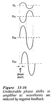
Audio (and other) signals at an amplifier input are usually made up of a combination of component waveforms with different amplitudes and different frequencies. So, any variation in amplifier-introduced phase shift will create distortion in the output waveform that is not present in the input.
To investigate the Effects of Negative Feedback in Amplifiers phase shift assume that the open-loop gain has a phase shift angle of ø, and that the closed-loop phase shift is øCL. Then,
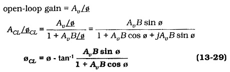
So,
negative feedback reduces ampler phase shift
by an angle of,
Noise:
Circuit noise generated within the feedback loop of an amplifier is reduced by a factor of (1 + AvB) in the same way that unwanted harmonics are reduced. It should be noted that only the noise generated within the feedback loop is reduced by feedback. Noise produced by bias resistors outside the feedback loop will not be affected by feedback.
Negative feedback reduces circuit noise.
Circuit Stability:
It is explained earlier that, for a circuit to oscillate, the loop phase shift must be 360° when the loop gain is 1. The loop phase shift is the phase shift around the loop from the amplifier input to the output, and back via the feedback network to the input. Similarly, the loop gain is the product of the amplifier open-loop gain and the feedback network attenuation, (AvB).
The loop phase shift of an amplifier can approach 360° as the gain falls off at the high end of the bandwidth. In this case, the amplifier might oscillate, and it is said to be unstable. The usual method of combating this kind of instability is to include small shunting capacitors from the transistor collector terminals to ground. These tend to cause the loop gain to fall below 1 before the loop phase shift approaches 360°.