Differential Pilot Wire Protection:
The Differential Pilot Wire Protection is based on the principle that under normal conditions, the current entering one end of a line is equal to that leaving the other end. As soon as a fault occurs between the two ends, this condition no longer holds and the difference of incoming and outgoing currents is arranged to flow through a relay which operates the circuit breaker to isolate the faulty line. There are several Differential Pilot Wire Protection schemes in use for the lines. However, only the following two schemes will be discussed
-
Merz-Price voltage balance system
-
Translay scheme
1. Men-Price voltage balance system: Fig. 23.8 shows the single line diagram of MerzPrice voltage balance system for the protection of a 3-phase line. Identical current transformers are placed in each phase at both ends of the line. The pair of CTs in each line is connected in series with a relay in such a way that under, normal conditions, their secondary voltages are equal and in opposition i.e. they balance each other.
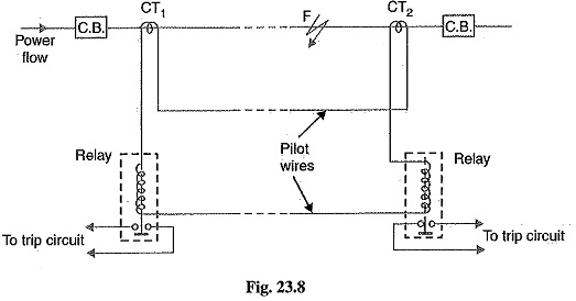
Under healthy conditions, current entering the line at one-end is equal to that leaving it at the other end. Therefore, equal and opposite voltages are induced in the secondaries of the CTs at the two ends of the line. The result is that no current flows through the relays. Suppose a fault occurs at point F on the line as shown in Fig. 23.8. This will cause a greater current to flow through CT1 than through CT2. Consequently, their secondary voltages become unequal and circulating current flows through the pilot wires and relays. The circuit breakers at both ends of the line will trip out and the faulty line will be isolated.
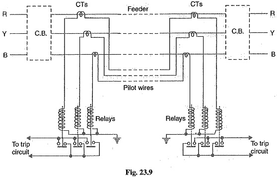
Fig. 23.9 shows the connections of Merz-Price voltage balance scheme for all the three phases of the line.
Advantages of Differential Pilot Wire Protection:
- This system can be used for ring mains as well as parallel feeders,
- This system provides instantaneous protection for ground faults. This decreases the possibility of these faults involving other phases.
- This system provides instantaneous relaying which reduces the amount of damage to overhead conductors resulting from arcing faults.
Disadvantages of Differential Pilot Wire Protection:
- Accurate matching of current transformers is very essential.
- If there is a break in the pilot-wire circuit, the system will not operate.
- This system is very expensive owing to the greater length of pilot wires required.
- In case of long lines, charging current due to pilot-wire capacitance effects may be sufficient to cause relay operation even under normal conditions.
- This system cannot be used for line voltages beyond 33 kV because of constructional difficulties in matching the current transformers.
2. Translay scheme: This system is similar to voltage balance system except that here balance or opposition is between the voltages induced in the secondary windings wound on the relay magnets and not between the secondary voltages of the line current transformers. This permits to use current transformers of normal design and eliminates one of the most serious limitations of original voltage balance system, namely ; its limitation to the system operating at voltages not exceeding 33 kV.
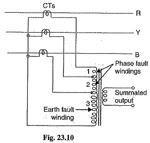
The application of Translay scheme for a single phase line has already been discussed in Art. 21.20. This can be extended to 3-phase system by applying one relay at each end of each phase of the 3-phase line. However, it is possible to make fur her simplification by combining currents derived from all phases in a single relay at each end, using he principle of summation transformer (See Fig. 23.10). A summation transformer is a device that reproduces the poly phase line currents as a single-phase quantity. The three lines CTs are connected to the tapped primary of summation transformer. Each line. CT energizes a different number of turns (from line to neutral) with a resulting single phase output. The use of summation transformer permits two advantages viz (i) primary windings 1 and 2 can be used for phase faults whereas winding 3 can be used for earth fault (ii) the number of pilot wires required is only two.
Schematic arrangement: The Translay scheme for the protection of a 3-phase line is shown in Fig. 23.11. The relays used in the scheme are essentially overcurrent induction type relays. Each relay has two electromagnetic elements. The upper element carries a winding (11 or 11 a) which is energized as a summation transformer from the secondaries of the line CTs connected in the phases of the line to be protected. The upper element also carries a secondary winding (12 or 12 a) which is connected is series with the operating winding (13 or 13 a) on the lower magnet. The secondary windings 12, 12 a and operating windings 13, 13 a are connected in series in such a way that voltages induced in them oppose each other.. Note that relay discs and tripping circuits have been omitted in the diagram for clarity.
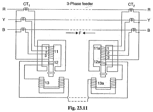
Operation: When the feeder is sound, the currents at its two ends are equal so that the secondary currents in both sets of CTs are equal. Consequently, the currents flowing in the relay primary winding 11 and 11 a will be equal and they will induce equal voltages in the secondary windings 12 and 12a. Since these windings are connected in opposition, no current flows in them or in the operating windings 13 and 13a. In the event of a fault on the protected line, the line current at one end must carry a greater current than that at the other end. The result is that voltages induced in the secondary windings 12 and 12 a will be different and the current will flow through the operating coils 13, 13a and the pilot circuit. Under these conditions, both upper and lower elements of each relay are energised and a forward torque acts on the each relay disc. The operation of the relays will open the circuit breakers at both ends of the line.
- Suppose a fault F occurs between phases R and Y and is fed from both sides as shown in Fig. 11. This will energise only section 1 of primary windings 11 and 11a and induce voltages in the secondary windings 12 and 12a. As these voltages are now additive, therefore, current will circulate through operating coils 13, 13a and the pilot circuit. This will cause the relay contacts to close and open the circuit breakers at both ends. A fault between phases Y and B energises section 2 of primary windings 11 and 11a whereas that between R and B will energise the sections 1 and 2.
- Now imagine that an earth fault occurs on phase R. This will energize sections 1, 2 and 3 of the primary windings 11 and 11a. Again if fault is fed from both ends, the voltages induced in the secondary windings 12 and 12a are additive and cause a current to flow through the operating coils 13, 13a. The relays, therefore, operate to open the circuit breakers at both ends of the line. In the event of earth fault on phase Y, sections 2 and 3 of primary winding 11 and 11a will be energised and cause the relays to operate. An earth fault on phase B will energise only section 3 of relay primary windings 11 and 11a.
Advantages
- The system is economical as only two pilot wires are required for the protection of a 3-phase line.
- Current transformers of normal design can be used.
- The pilot wire capacitance currents do not affect the operation of relays.