Busbar Protection:
Busbars and lines are important elements of electric power system and require the immediate attention of protection engineers for safeguards against the possible faults occurring on them. The methods used for the protection of generators and transformers can also be employed, with slight modifications, for the busbars and lines. The modifications are necessary to cope with the protection problems wising out of greater length of lines and a large number of circuits connected to a Busbar Protection. Although differential protection can be used it becomes too expensive for longer lines due to the greater length of pilot wires required. Fortunately, less expensive methods are available which are reasonably effective in providing protection for the busbars and lines. In this chapter, we shall focus our attention on the various methods of protection of busbars and lines.
Busbar Protection in the generating stations and sub-stations form important link between the incoming and outgoing circuits. If a fault occurs on a busbar, considerable damage and disruption of supply will occur unless some form of quick-acting automatic protection is provided to isolate the faulty busbar. The busbar zone, for the purpose of protection, includes not only the busbars themselves but also the isolating switches, circuit breakers and the associated connections. In the event of fault on any section of the busbar, all the circuit equipment connected to that section must be tripped out to give complete isolation.
The standard of construction for Busbar Protection has been very high, with the result that bus faults are extremely rare. However, the possibility of damage and service interruption from even a rare bus fault is so great that more attention is now given to this form of protection. Improved relaying methods have been developed, reducing the possibility of incorrect operation.
The two most commonly used schemes for busbar protection are :
-
Differential Protection
-
Fault Bus Protection
1. Differential Protection: The basic method for busbar protection is the differential scheme in which currents entering and leaving the bus are totalised. During normal load condition, the sum of these currents is equal to zero. When a fault occurs, the fault current upsets the balance and produces a differential current to operate a relay.
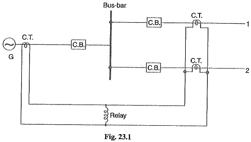
Fig. 23.1 shows the single line diagram of current differential scheme for a station busbar. The Busbar Protection is fed by a generator and supplies load to two lines. The secondaries of current transformers in the generator lead, in line 1 and in line 2 are all connected in parallel. The protective relay is connected across this parallel connection. All CTs must be of the same ratio in the scheme regardless of the capacities of the various circuits. Under normal load conditions or external fault conditions, the sum of the currents entering the bus is equal to those leaving it and no current flows through the relay. If a fault occurs within the protected zone, the currents entering the bus will no longer be equal to those leaving it. The difference of these currents will flow through the relay and cause the opening of the generator, circuit breaker and each of the line circuit breakers.
2. Fault Bus Protection: It is possible to design a station so that the faults that develop are mostly earth-faults. This can be achieved by providing earthed metal barrier (known as fault bus) surrounding each conductor throughout its entire length in the bus structure. With this arrangement, every fault that might occur must involve a connection between a conductor and an earthed metal By directing the flow of earth-fault current, it is possible to detect the faults and determine their location. This type of protection is known as fault bus protection.
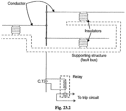
Fig. 23.2 show the schematic arrangement of fault bus protection. The metal supporting structure or fault bus is earthed through a current transformer. A relay is connected across the secondary of this CT. Under normal operating conditions, there is no current flow from fault bus to ground and the relay remains inoperative. A fault involving a connection between a conductor and earthed supporting structure will result in current flow to ground through the fault bus, causing the relay to operate. The operation of relay will trip all breakers connecting equipment to the bus.
Protection of Lines:
The probability of faults occurring on the lines is much more due to their greater length and exposure to atmospheric conditions. This has called for many protective schemes which have no application to the comparatively simple cases of alternators and transformers. The requirements of line protection are :
- In the event of a short-circuit, the circuit breaker closest to the fault should open, all other circuit breakers remaining in a closed position.
- In case the nearest breaker to the fault fails to open, back-up protection should be provided by the adjacent circuit breakers.
- The relay operating time should be just as short as possible in order to preserve system stability, without unnecessary tripping of circuits.
The protection of lines presents a problem quite different from the protection of station apparatus such as generators, transformers and Busbar Protection. While differential protection is ideal method for lines, it is much more expensive to use. The two ends of a line may be several kilometers apart and to compare the two currents, a costly pilot-wire circuit is required. This expense may be justified but in general less costly methods are used. The common methods of line protection are :
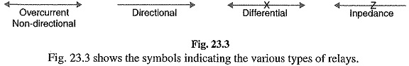
- Time-graded overcurrent protection
- Differential protection
- Distance protection