Basic Radar System Block Diagram:
Basic Radar System Block Diagram consists of a transmitter and a receiver, each connected to a directional antenna. The transmitter is capable of sending out a large UHF or microwave power through the antenna. The receiver collects as much energy as possible from the echoes reflected in its direction by the target and then processes and displays this information in a suitable way. The receiving antenna is very often the same as the transmitting antenna. This is accomplished through a kind of time-division multiplexing arrangement, since the radio energy is very often sent out in the form of pulses.
Fundamentals of Basic Radar System:
Basic radar system: The operation of a Basic Radar System Block Diagram can be quite complex, but the basic principles are somewhat easy for the student to comprehend. Covered here are some fundamentals which will make the follow-up material easier to digest.
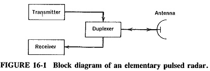
Refer to Figure 16-1 and the timing diagram (Figure 16-2). A master timer controls the pulse repetition frequency (PRF) or pulse repetition rate (PRR) (Figure 16-2.). These pulses are transmitted by a highly directional parabolic antenna at the target, which can reflect (echo) some of the energy back to the same antenna. This antenna has been switched from a transmit mode to a receive mode by a duplexer. The reflected energy is received, and time measurements are made, to determine the distance to the target.
The pulse energy travels at 186,000 statute miles per second (162,000 nautical miles per second). For convenience, a radar mile (2000 yd or 6000 ft) is often used, with as little as 1 percent error being introduced by this measurement. The transmitted signal takes 6.16 μs to travel 1 radar mile; therefore the round trip for 1 mi is equal to 12.36μs. With this information, the range can be calculated by applying Equation (16-1).
![]()
Where
t = time from transmitter to receiver in microseconds
For higher accuracy and shorter ranges, Equation (16-2) can be utilized.
![]()
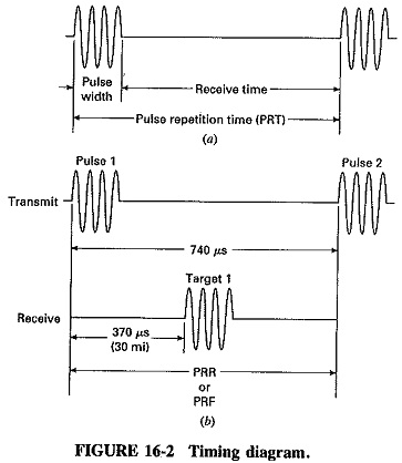
After the radar pulse has been transmitted, a sufficient rest time (Figure 16-2a) (receiver time) must be allowed for the echo to return so as not to interfere with the next transmit pulse. This PRT, or pulse repetition time, determines the maximum distance to the target to be measured. Any signal arriving after the transmission of the second pulse is called a second return echo and would give an ambiguous indication.
The range beyond which objects appear as second return echoes is called the maximum unambiguous range (mur) and can be calculated as shown in Equation (16-3).

Range in miles; PRT in μs
Refer to the timing diagram (Figure 16-2). By calculation, maximum unambiguous distance between transmit pulse I and transmit pulse 2 is 50 mi. Any return pulse related to transmit pulse 1 outside this framework will appear as weak close-range pulses related to transmit pulse 2. The distance between pulse 1 and pulse 2 is called the maximum range.
If a large reflective object is very close, the echo may return before the complete pulse can be transmitted. To eliminate ambiguity, the receiver is blocked, or turned off. Blocking of the receiver during the transmit cycle is common in most Basic Radar System Block Diagram.
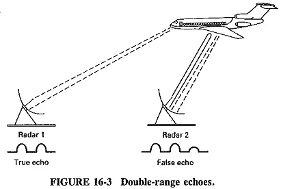
A second problem arises-with large objects at close range. The transmitted pulse may be reflected by the target for one complete round trip (see Figure 16-3). It may then, because of its high energy level, be reflected by the transmitter antenna and bounced back to the target for a second round trip. This condition is called double range echoes. To overcome this form of ambiguity, Equation (16-4) is used to determine the minimum-effective range.
Other terms sometimes discussed in conjunction with the radar transmitter are duty cycle, peak power, and average power. To calculate duty cycle the following equation may be employed.
![]()
The ratio of peak power and average may also be expressed in terms of “duty cycle.”
To complete this section on fundamentals, we can conclude that in order to produce, a strong echo over a maximum range, high peak power is required. In some situations, size and heat are important factors (radar in aircraft) and low average power is a requirement. We can easily see how low duty cycle is an important consideration.
Commenting briefly on the other aspects of the radar set, we find that pulse-modulated magnetrons, klystrons, TWTs or CFAs are normally used as transmitter output tubes, and the first stage of the receiver is often a diode mixer. The antenna generally uses a parabolic reflector of some form.
Development of Radar:
From its inception, Basic Radar System Block Diagram has used a system of sending short, powerful pulses of radio energy and then analyzing the returned echoes to determine the position, distance and possibly velocity of the target. However, the methods of doing so have evolved and become far more refined and sophisticated as time has gone by. The primary incentive was the imminence of war. Radar was made possible by a technology which, at the time war broke out, was just beginning to show promise. This technology itself took great strides forward to meet the new challenges imposed by war.
The first radars worked at much lower frequencies than present systems (as low as 60 MHz for the original British coastal air-warning radar) because of a lack of sufficiently powerful transmitting tubes at higher frequencies. This was changed in 1940 with the appearance of the cavity magnetron, and the stage was then set for the development of modern radar. One of the prime requirements of a Basic Radar System Block Diagram is that it should have a fair degree of accuracy in its indication of target direction. This is possible only if the antennas used are narrow-beam ones, i.e., have dimensions of several wavelengths. That requirement cannot be fulfilled satisfactorily unless the wavelengths themselves are fairly short, corresponding to the upper UHF or microwave frequencies.
The advent of the magnetron also made possible the next steps in the evolution of radar, namely, airborne radar for the detection of surface vessels and then airborne aircraft interception radar. In each of these, tight beams are necessary to prevent the receiver from being swamped by ground reflections, which would happen if insufficient discrimination between adjacent targets existed. Microwave radar for antiaircraft fire control was quickly developed, of which the most successful ground-based version was the U.S. Army’s SCR-584. It was capable of measuring the position of enemy aircraft to within 0.1°, and the distance, or range, to within 25 m. Such radars were eventually capable of tracking targets by locking onto them, with the aid of servomechanisms controlling the orientation of the antennas. Anti-surface vessel (ASV) radars became very common and quite accurate toward the end of the war. So did airborne radar for navigation, bombing or bomber protection; electronic navigation systems were also developed. Radar countermeasures were instituted, consisting mainly of jamming (transmission of confusing signals at enemy radar) or the somewhat more effective dropping of aluminum foil, in strips of about a half-wavelength, to cover approaching aircraft by producing false echoes. This “chaff” (American) or “window” (British) proved very effective, but its use in the war was considerably delayed. Each side thought that the other did not know about it and so it was kept secret; however, it eventually came to be used on a very large scale. One of the indications of the enormous growth in the importance of radar in World War II is the increase in the staff of the U.S. Army’s Radiation Laboratory. It started with about 40 people in 1941, and numbers multiplied tenfold by 1945.
The subsequent developments of radar have also been numerous. They have included the use of wavelengths well into the millimeter range, at which atmospheric interference becomes noticeable but see also Figure 8-3 for the presence of radar “windows.” We have witnessed the use of greater powers at all wavelengths and the use of computers for a number of applications (especially fire control) to improve accuracy and reduce the time lag of manual operation. Long-range, fixed early-warning radars have been built, including the MEWS and BMEWS systems. These Basic Radar System Block Diagram use huge antennas and enormous transmitting powers and are supplemented by radar-carrying high-flying aircraft, which have an extended radar horizon because of their height. Satellites carrying radar have been employed for military purposes, such as early detection of ballistic missiles, and civilian uses, notably in meteorology and mapping. Other important civilian uses of radar have included coastal navigation for shipping, position finding for shipping and aircraft, and air-traffic control at airports. This has extended the use of the landing facilities to weather conditions which would have made them unusable without radar and its allied systems. Also, the use of radar by various police forces, for the control of traffic speed and the prosecution of offenders, is becoming commonplace.
Numerous scientific advances have been made with the aid of radar; for instance, as early as in 1945 an error of 900 m was found (by accident) in the map position of the island of Corsica. More recent scientific uses of radar on an interplanetary scale have yielded much useful information about the sun and the rest of the solar system, and especially about the distances and rotations of the various planetary bodies. For example, it is now known that the planet Mercury rotates with a speed not equal to its angular orbital velocity, so that it does not always present the same face to the sun.
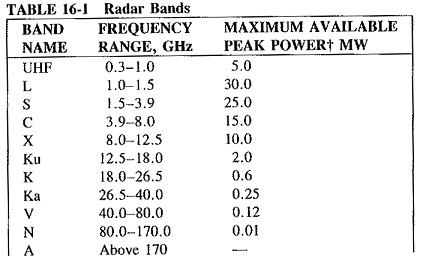
Frequencies and Powers used in Radar:
The frequencies employed by Basic Radar System Block Diagram lie in the upper UHF and microwave ranges. As a result of wartime security, names grew up for the various frequency ranges, or bands, and these are still being used. One such term has already been discussed (the X band), and the others will now be identified. Since there is not a worldwide agreement on radar band nomenclature, the names used in Table 16-1 are the common American designations.