What is PWM Inverter?
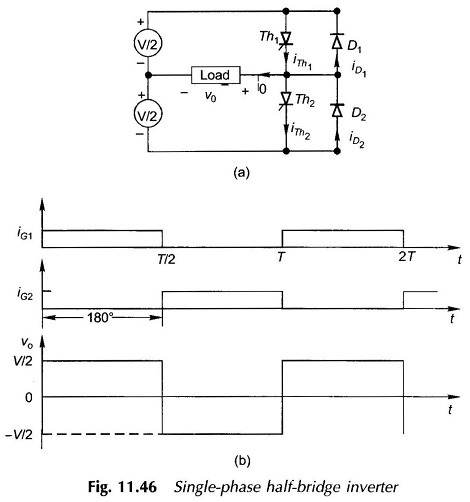
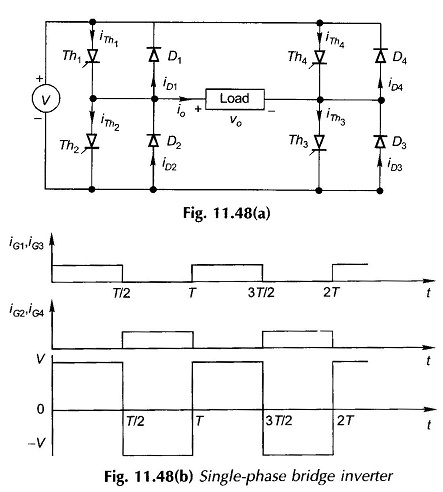
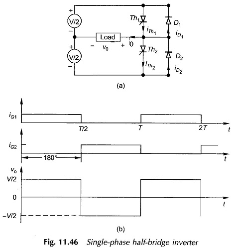
What is PWM Inverter?: What is PWM Inverter? - In presenting the arguments here attention will be focused on a single-phase inverter. Instead of the single rectangular pulse output of Figs 11.46 and 11.48 during…
Comments Off on What is PWM Inverter?
November 3, 2016