Wagner Ground Connection:
Wagner Ground Connection – When performing measurements at high frequency, stray capacitances between the various bridge elements and ground, and between the bridge arms themselves, become significant. This introduces an error in the measurement, when small values of capacitance and large values of inductance are measured.
An effective method of controlling these capacitances, is to enclose the elements by a shield and to ground the shield. This does not eliminate the capacitance, but makes it constant in value.
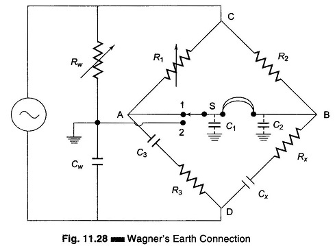
Another effective and popular method of eliminating these stray capacitances and the capacitances between the bridge arms is to use a Wagner Ground Connection. Figure 11.28 shows a circuit of a capacitance bridge. C1 and C2 are the stray capacitances. In Wagner’s Ground Connection, another arm, consisting of Rw and Cw forming a potential divider, is used. The junction of Rw and Cw is grounded and is called Wagner Ground Connection. The procedure for adjustment is as follows.
The detector is connected to point 1 and R1 is adjusted for null or minimum sound in the headphones. The switch S is then connected to point 2, which connects the detector to the Wagner ground point. Resistor Rw is now adjusted for minimum sound. When the switch `S’ is connected to point 1, again there will be some imbalance. Resistors R1 and R3 are then adjusted for minimum sound and this procedure is repeated until a null is obtained on both switch positions 1 and 2. This is the ground potential. Stray capacitances C1 and C2 are then effectively short-circuited and have no effect on the normal bridge balance.
The capacitances from point C to D to ground are also eliminated by the addition of Wagner’s ground connection, since the current through these capacitors enters Wagner’s ground connection.
The addition of the Wagner ground connection does not affect the balance conditions, since the procedure for measurement remains unaltered.