Semiconductor Converter Controlled Drives:
These are now widely used both in ac and dc tractions involving dc and ac motors, and the conventional drives have all become outdated, and will be phased out in near future. The Semiconductor Converter Controlled Drives have several advantages. Some of their common advantages are listed below:
- High efficiency.
- Low maintenance requirements due to absence of moving parts.
- Better adhesion due to stepless control of motor torque and fast response of semiconductor Wheel-slip control is very simple.
- Higher acceleration, deceleration and speed due to better adhesion.
- Increased comfort of passengers due to smooth acceleration and braking.
- Flexible control, which makes it amenable to micro computer/microprocessor/programmable logic controller control, leading to optimal and efficient performance.
- Easy maintenance, repair and fault diagnosis.
- Interfaces more readily with automatic train control.
- Longer life.
- Some form of torque control is used, which allows a performance to some extent independent of line voltage and passenger weight, both during motoring and braking.
Several types of Semiconductor Converter Controlled Drives have been developed. The commonly used drives. All these drives are operated with closed-loop torque control. As sensing the torque directly is difficult, the torque control is affected indirectly. In the case of dc drive it takes the form of closed-loop current control as the torque is a function of current. In case of induction motors, the torque control is effected with the help of either stator current or rotor slip-speed control. The traction drives are also operated with inner torque control and outer speed control loops.
The 25 KV AC Traction using Semiconductor Converter Controlled Drives DC Motors:
The simplest arrangement consists of a half-controlled converter feeding dc series traction motors, as shown in Fig. 10.13.
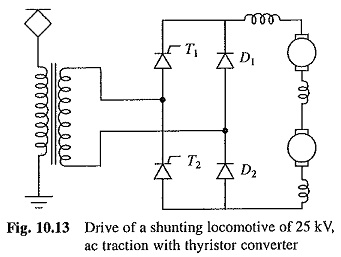
Such an arrangement is sometimes used in low power shunting locomotives. It suffers from two important limitations. First, at low output voltages the converter power factor is low. Secondly, the source current with square wave shape is rich in harmonics. The rapid changes at the leading and trailing edges of the source current cause sharp harmonic disturbances in the supply network and telecommunication lines. The frequency range of harmonics is determined by the steepness of these edges, and their amplitudes by the magnitude of the step. Because of the low power rating of a shunting locomotive, the poor power factor, harmonics and harmonic disturbances have only marginal effect on the supply network and telecommunication lines, therefore, such a simple arrangement (Fig. 10.13) is found acceptable. In case of suburban and main line trains power rating is large, consequently the adverse effects of the poor power factor, harmonics and harmonic disturbances on the supply network and telecommunication lines are unacceptable. To overcome these limitations multistage converters, which are operated with sequence control, are used to feed armatures of traction motors. Two forms of two stage converters are shown in Figs. 10.14 and 10.16.
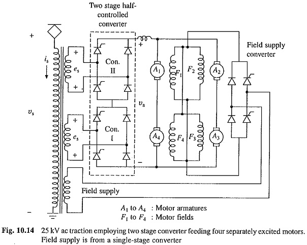
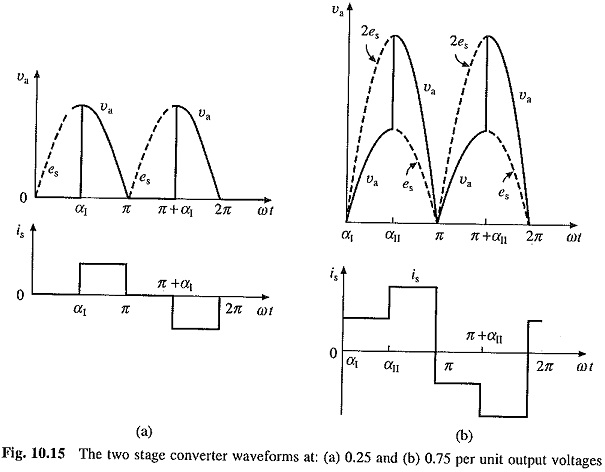
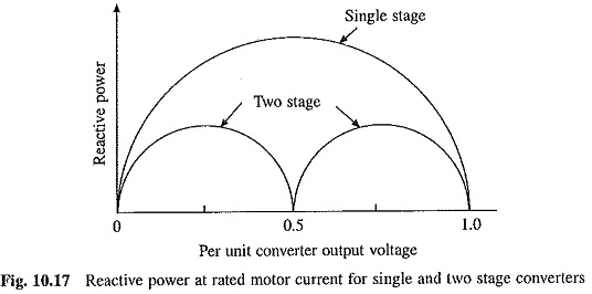
The two-stage converter of Fig. 10.14 uses two half-controlled converters connected in series. A transformer with two identical secondaries, feeds the half-controlled converters. For dc output voltage from 0 to half, only converter I is controlled and converter II is bypassed by its diodes. Figure 10.15a shows the waveforms of dc output voltage and the source current for the converter I firing angle α1 = 90°. At half of full-output voltage, α1 = 0°. For the output voltage between half and full, α1 is retained at 0° and the firing angle of converted II is controlled between 180 and 0°. Figure 10.15(b) shows the converter output voltage and source current waveforms for α1 = 0 and α11 = 90°. The jump in source current is now reduced to half compared to the single stage converter of Fig. 10.13. Considerable reduction in reactive power, leading to improvement in power factor, is obtained. A comparison of reactive power at rated motor current is shown in Fig. 10.17 for single stage and two stage control. Field supply, as shown in Fig. 10.14, is obtained from single stage half-controlled converter.
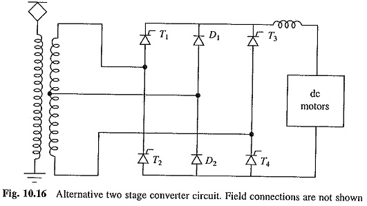
The operation, waveforms and performance of converter of Fig. 10.16 are identical to the converter of Fig. 10.14. The series circuit of Fig. 10.14 requires devices which will withstand half the circuit voltage, but then it requires a transformer with two secondary windings. The converter of Fig. 10.16 requires only a single centre-tapped secondary winding but the devices have to withstand full circuit voltage. In main line traction several pairs of two series connected motors are employed (Fig. 10.12 or 10.14), consequently the converter output voltage falls in the range of 1000 to 1500 V dc. The converter of Fig. 10.14 is found more economical for this application. In some EMU (suburban) applications all motors are connected in parallel. Therefore, the converter output voltage is in the range of 500 to 750 V dc. The converter of Fig. 10.16 is found more economical for this application.
Above description is for two stage converters. Performance can be improved further by increasing the converter stages beyond two. Converters up to four stages have been reported. However, the benefits gained in adding each stage diminishes as the number of stages is increased beyond two. In practice, the use of more than two stages becomes uneconomical because of the proportionate increase in the number of devices and transformer secondaries.
In Fig. 10.14 four separately excited motors are shown. The number of motors depends on ratings and they are connected in different combinations depending on application and manufacturer’s preferences. EMUs (electrical multiple units) in Madras suburban trains employ four series motors connected in two parallel pairs with each pair having two series connected motors. A 4000 HP locomotive designed by BHEL uses six series motors connected to form three parallel pairs with each pair having two motors in series.
For EMU (suburban trains) converters, which are relatively of low power rating (around 1500 kVA), it has been found that the simple two stage converter of Fig. 10.14 requires no additional steps to reduce harmonics and improve power factor. However, this is not the case with the more powerful converters required for locomotives. For locomotives, harmonic filter is connected at the input terminals of each converter to reduce harmonics, both low frequency and high frequency, to prevent interference with telecommunication lines and track circuit and to reduce harmonic disturbance in the supply network. Thyristor switched capacitors with two stages are employed to ensure that the power factor does not fall below 0.8. Such a scheme has been used in Hitachi Locomotive. Recent trend has been to use gate turn-off thyristors (GT0s) instead of thyristors and to operate the converter with an appropriate pulsewidth modulation technique. This operation allows the converter operation at unity fundamental power factor throughout and simplifies the harmonic filter design but reduces efficiency.
In order to obtain smooth acceleration and good adhesion, both in locomotives and EMUs, the converter is operated with closed-loop current control. A master controller sets the current reference which is compared with the actual converter output current. The error is used to adjust the converter firing angles so that the actual current is maintained equal to the reference current throughout the accelerating range. An additional loop may be provided for limiting maximum acceleration. This avoids jerks and consequent inconvenience to the passengers. As the torque during acceleration is controlled steplessly, high acceleration and good adhesion are obtained.
Wheel-slip control may be easily incorporated here by having provision for master controller to set the current reference to zero whenever the wheel-slip is detected.
Because of flexible control many other features can be easily incorporated such as complete automatic control and fault detection. Programmable logic controllers, microprocessors or microcomputers can be utilised for this purpose.
Dynamic braking can be incorporated in both separately excited and series excited motors. In case of separately excited motors, fixed resistors are connected across the armature and converter is disconnected. The braking torque is controlled by controlling the field current. Controlling the field current is not a problem because fields are in any case fed from controlled rectifiers. For dynamic braking, series motors are also connected for separate excitation. Field windings connected in series are fed from one of the converters and the converter is supplied by another step down transformer with low output voltage, because of the low resistance of field windings. Fixed resistors are connected across the armature. Braking torque is controlled by controlling the field current.
Braking performance with field current control and fixed resistors across armatures is inferior compared to control with full field and switched (or sectionalised) resistors across the armature.
Theoretically regenerative braking can be used by replacing half controlled converters of Fig. 10.14 by fully controlled converters. But it is generally not used because of two problems:
- A thyristor converter uses line voltage for commutation. The commutation failure can occur during braking due to following: (i) loss of supply, (ii) pantograph contact bounce or (iii) while passing through neutral sections. Then thyristors conduct continuously giving a short circuit both on ac and dc terminals. This problem is overcome when thyristors are replaced by GTOs (gate turn-off thyristors).
- Cost of the locomotive and transmission equipment increases, because with regenerative braking their voltage ratings go up by 10 to 15%.